
Contents:
D) Surface Runner and gate Design Standards
E) Hot Runner Design Guidelines
F) Three plate runner and Pin-Point gate design Standards
A) Surface Runner and gate Design Standards
1) Viewmold will NOT specify runner or gate size/configuration without a MOLD FLOW ANALYSIS performed by a reputable source and close
documented communication with the Customer. Unless clearly documented on the mold quotation and agreed to by Viewmold, the Customer will specify the runner and
gate size/configuration and be responsible for part production cycle times.
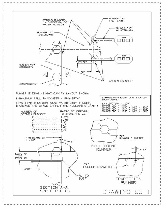
2) Trapezoidal runners are preferred due to ease of machining and design. Full round runners are acceptable and common,
and are necessary with some material types. All runner intersections will have radii added in the direction of flow and have cold slugs at each intersection.
Refer to drawing S3-1 for cold runner design guidelines.
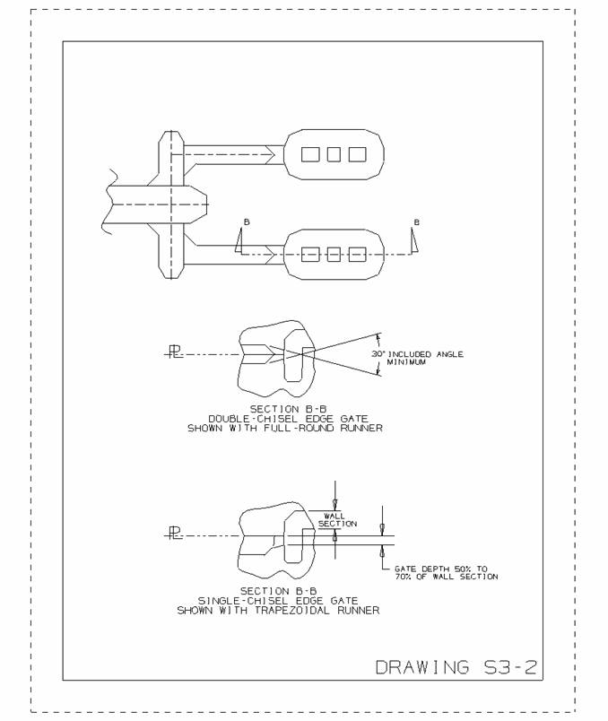
3) Edge gate designs are to be the “double chisel” type that can easily be detached from the part. Refer to
drawing S3-2 for edge gate design guidelines.
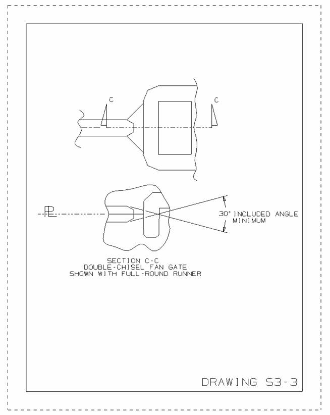
 4) Fan gates are commonly used to assist in reducing part warp or to maintain flatness. Refer to drawing S3-3 for fan gate
design guidelines.
4) Fan gates are commonly used to assist in reducing part warp or to maintain flatness. Refer to drawing S3-3 for fan gate
design guidelines.
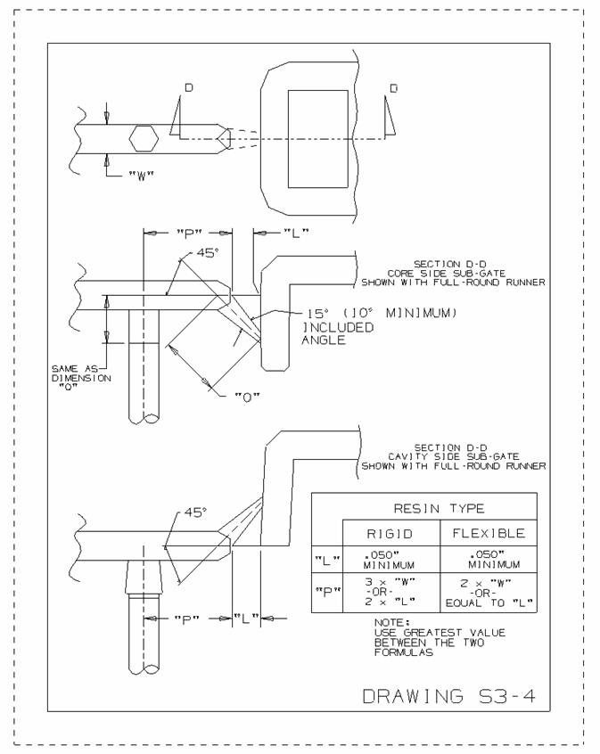
5) Sub-gate designs vary, and should be addressed on an individual basis. Refer to drawing S3-4 for sub-gate design guidelines.
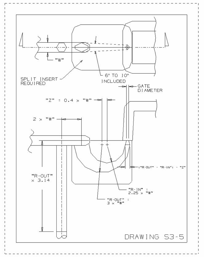
 6) Tunnel (“Cashew”) gates can only be used with specific material types. Refer to drawing S3-5 for “
Cashew” gate design guidelines.
6) Tunnel (“Cashew”) gates can only be used with specific material types. Refer to drawing S3-5 for “
Cashew” gate design guidelines.
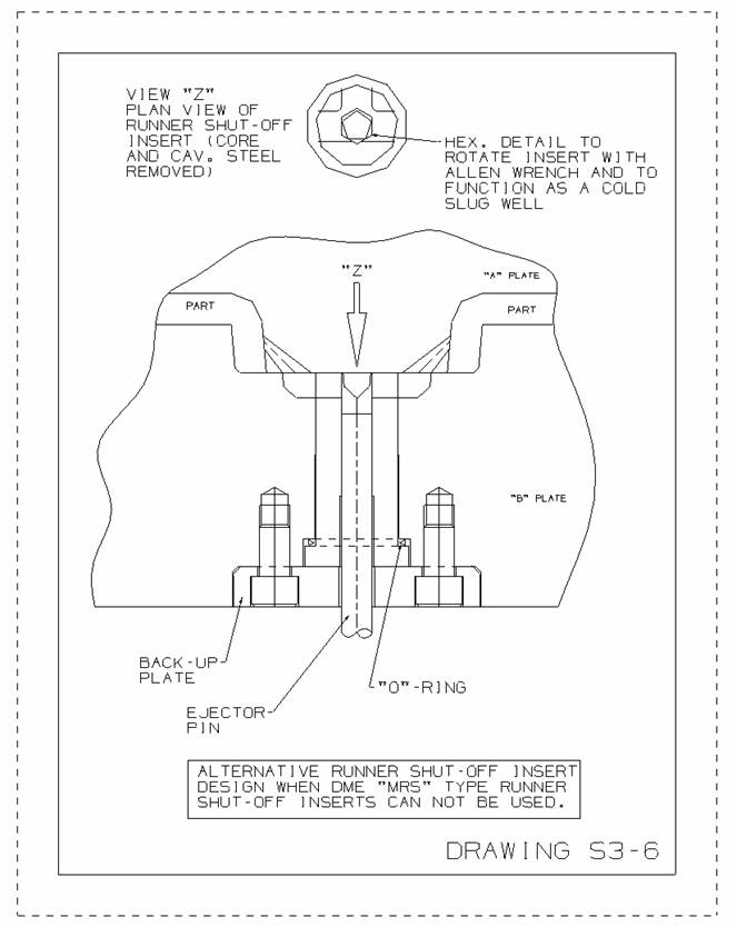
7) Runner shut-off inserts will be the DME “MRS” Type. When the DME “MRS” Type is not useable,
refer to drawing S5-6 for an alternative custom design.
B) Hot Runner Design Guidelines
1) The Customer will specify the Hot Runner Supplier. Husky, Incoe, Mold Masters, DME, and Synventive are the preferred Hot
Runner suppliers at Viewmold. Any Hot Runner suppliers not listed must be approved by the Engineering Manager and specified by the Customer. Viewmold will NOT
specify flow channel, nozzle type, or gate size/configuration without a MOLD FLOW ANALYSIS performed by the hot runner supplier or by a reputable source and close
documented communication with the Customer. Unless clearly documented on the mold quotation and agreed to by Viewmold, the Customer and hot runner supplier will
specify the flow channel, nozzle type, and gate size/configuration and be responsible for part production cycle times.
2) All manifold pocket and nozzle-well machining tolerances as specified by the Hot Runner supplier will be adhered to
by Viewmold.
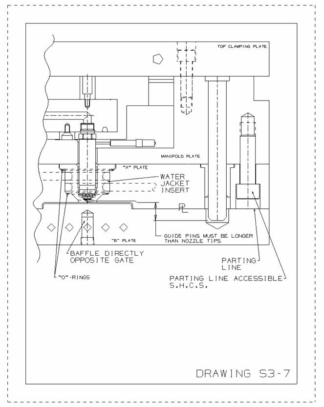
3) Temperature control of at the nozzle well/gate detail is critical. Water is to be designed as close as possible to the nozzle
well/gate without compromising the surrounding steel. Consider water jackets in all designs as the mold quotation allows (refer to drawing S3-7). Provide a
cooling baffle opposite the gate, preferably on a separate cooling circuit.
4) In cases where nozzle cleaning is necessary in the molding press, the system will be designed with parting line accessible
S.H.C.S. to disassemble the hot runner system plate assembly as shown in drawing S3-7. Guide pins must be longer than the Nozzle tips to protect the nozzle tips
during assembly/disassembly of the “hot half”.
C) Three Plate Runner and Pin-Point Gate Design Standards
1) DME Three plate extension bushings will be used.
2) Trapezoidal runner configurations are preferred. Viewmold will NOT specify runner or pin-point gate size/configuration without
a MOLD FLOW ANALYSIS performed by a reputable source and close documented communication with the Customer. Unless clearly documented on the mold quotation and
agreed to by Viewmold, the Customer will specify the runner and pin-point gate size/configuration and be responsible for part production cycle times.
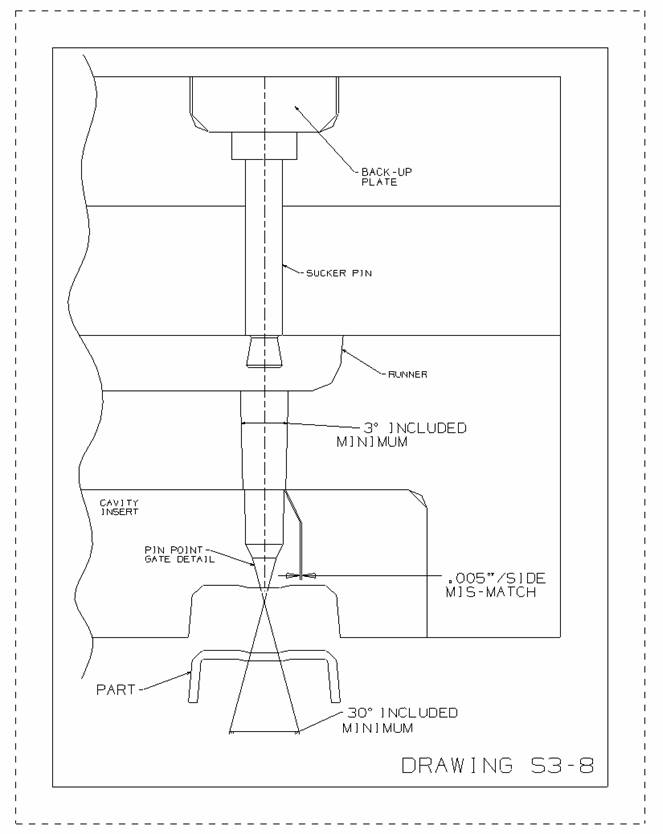
3) Pin Point gates need to be designed so that the gate will break off at the desired location. A gate indent (spherical
radius detail) is needed to allow for the vestige “carrot” left at the part surface. Refer to drawing S3-8 for details.
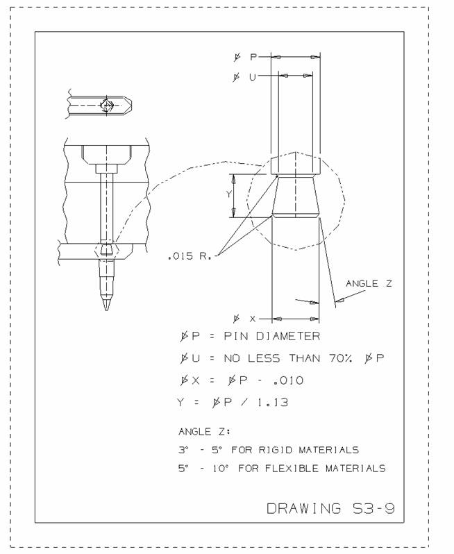
 4) Sucker Pin design and location is critical, and the design is very dependant on the plastic material specifications. Refer to drawing S3-9 for details.

Injection Mold slide lifter standards
Injection Mold runner standards
Injection Mold cooling standards
Injection Mold venting standards
Injection Mold Ejector System standards standards
Injection Mold component standards
Injection Mold Hydraulic and Pneumatic standards
Injection Mold Design Check standards
Injection Mold Steel Grades standards
Injection Mold inspection standards