
F) injection mold ejector pin design standards
G) injection mold Guided ejection design standards
H) injection mold Spring return standards
I) injection mold Hydraulic ejector standards
J) injection mold Press Knock-out (PKO) design standards
A) injection mold ejector pin design standards
1) No ejector pins smaller than .093” (3/32”) diameter are to be used. 3/32” DIA. EJECTOR PINS MUST BE THE 2” SHOULDER TYPE.
2) Use the largest size ejector pin possible.
3) Ejector pins should be cleared to within ¾” of molding surface.
4) Ejector pins should be designed to “PUSH” the part, NOT “PULL” the part.
5) Ejector pin “bosses” can be used only with Customer approval of size and locations. Normally these “bosses” will cause part sink or distortion, therefore use with caution.
6) Ejector pins and Pin Plate must be like- numbered for ease of assembly.
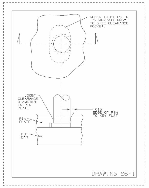
7) All contoured ejector pins must be keyed to prevent rotation by a pocket in the pin plate (refer to drawing S6-1). NO DOWELS WILL BE USED FOR KEYS.
8) All ejector pins must be DME “EX” type or equivalent.
9) There can be no ejection under a slide or lifter detail without written Customer approval. If the customer accepts ejection under a slide or lifter detail, limit switches must register both forward and back movement of the ejector system. DME standard “Thin Switch” limit switches are acceptable.
10) National standard Ejector Blades and Ejector Blade shanks (two piece design) or equivalent are to be used. Other standard single piece Ejector Blade types can be used if necessary.
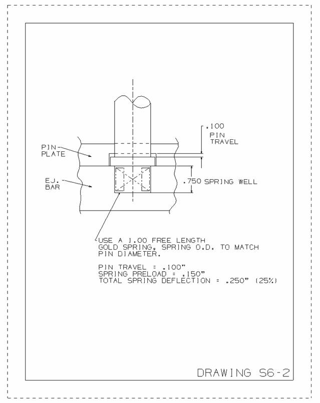
11) Rectangular ejectors and push bars can be used. In cases where the rectangular ejectors and push bars contact the parting line, the return pins must be pre-loaded with a spring behind the head with a minimum of .100” preload (refer to drawing S6-2).
B) injection mold Guided ejection design standards
1) Ejector plates must be guided with two ejector guide pins and ejector guide bushings minimum. Four Guide Pins and Bushings are considered standard, and “normal practice”. The amount and size will be determined based on the mold size and number of ejector plate activated actions.
2) Guide pins will be DME Standard Guided Ejection Leader Pins (DME “PF” or “GL” type).
3) Guide Bushings will be DME Standard Bronze Plated Guided Ejection Bushings (DME “GEB” type).
C) injection mold Spring return standards
1) Spring return will only be designed when specified by the Customer.
2) Use DME standard medium duty (blue) mold and die springs or equivalent. Total spring compression should never exceed 35% of the free length. Spring pre-load should be designed to provide twice the weight of the ejector bar/pin plate assembly if possible.
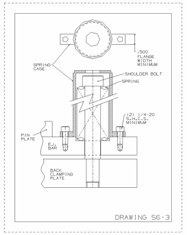
3) If external springs are used, provide spring cages securely installed on the pin plate with S.H.C.S. (refer to drawing S6-3).
4) In cases where the rectangular ejectors and push bars contact the parting line, the return pins must be pre-loaded with a spring behind the head with a minimum of .100” preload (refer to drawing S6-2).
D) injection mold Hydraulic ejector standards
1) Parker Series 2-H Hydraulic Cylinders will be used. The selection of cylinder bore size and cylinder mount style will be determined by mold size and the amount of ejector plate activated actions. Viewmold normally uses a style “JJ” mount. DO NOT USE PARKER MOUNTING STYLE “J” or “JB” DUE TO THE DECREASE IN PRESSURE RATING.
2) “T” style couplings will be used to secure the cylinder rod end to the Back Clamping Plate. (Refer to drawing S6-4)
3) Use Parker “EPS” style solid-state proximity switches mounted directly to the cylinder, or DME Standard “Thin Switch” limit switches mounted to the mold plates to register forward and back ejector plate travel.
4) Hydraulic cylinders used to activate the ejector system will be plumbed into a common port for “push” and “pull” sequence. The mold rails or sub-plates can be used as a hydraulic manifold.
E) Press Knock-out (PKO) design standards
1) The PKO pattern will be designed press specific for Viewmold (refer to SECTION 9: Molding Machine Standards).
2) 3.50” “diamond” and 4” x 16” patterns have 1.25” diameter clearance through the Back Clamping Plate. 6” x 28” pattern and above have 2.25” diameter clearances through the Back Clamping Plate. Viewmold PKO tap size for all patterns is 5/8”-11 or ½”-13.
3) When PKO extensions are specified, Progressive standard “Hex Series” extensions or “puck” style extensions are to be used.

Injection Mold design guideline
Injection Mold slide lifter standards
Injection Mold runner standards
Injection Mold cooling standards
Injection Mold venting standards
Injection Mold Ejector System standards standards
Injection Mold component standards
Injection Mold Hydraulic and Pneumatic standards
Injection Mold Design Check standards
Injection Mold Steel Grades standards
Injection Mold inspection standards