
Defines methods to provide optimum mold temperature control
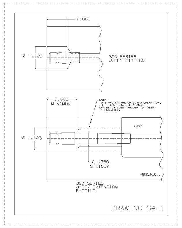
1) All molds must be recessed for DME 300 Series Jiffy Quick Disconnects or equivalent Counter bores will be 1.125” diameter to
allow for socket. (Refer to drawing S4-1)
 2) All mold actions requiring cooling must have ½” I.D. reinforced flexible hoses routed to outside without interference.
Jiffy-Tite extension plugs are preferred when possible.
2) All mold actions requiring cooling must have ½” I.D. reinforced flexible hoses routed to outside without interference.
Jiffy-Tite extension plugs are preferred when possible.
3) In cases where water manifolds are required, CITO type manifolds are preferred.
4) Use DME standard 300 Series male Jiffy-Tite plugs and 300 Series Jiffy-Tite Extension Plugs or equivalent.
5) All baffles are to be DME standard brass plug baffles or equivalent. NO PRESS-FIT BLADES ARE TO BE USED.
6) All pipe plugs are to be brass. Do not use expandable plugs with “o”-rings.
7) All water lines are to be clear of all obstructions. All circuits are to be air checked with 100 lbs. air pressure
per square inch.
8) No waterlines are to be less than ¼” from ejector pins or tapped holes. Avoid designing water directly
under tapped holes. Water should be spaced no less than 5/8” from molding surfaces where possible.
9) The amount of water and spacing of water circuits is determined on a custom basis. All considerations will be given to
provide the maximum water coverage possible, balancing optimum cooling and optimum ejection. Any areas that are difficult to cool should be considered
for sub-inserting with MOLDMAX. All MOLDMAX inserts must be cooled to provide efficient transfer of heat.
10) Water connections must not interfere with mold clamping ledges.
11) Stamp water circuits In and Out. (Example: “IN 1” “OUT 1”)
12) Standard water line drill and NPT taps:
.25” (1/4”) diameter with 1/16”-NPT
.34” (11/32”) diameter with 1/8”-NPT
 .43” (7/16”) diameter with ¼”-NPT
.56” (9/16”) diameter with 3/8”-NPT
.68” (11/16”) diameter with ½”-NPT
.93” (15/16”) diameter with ¾”-NPT
1.15” (1-5/32”) diameter with 1”-NPT
1.50” (1-1/2”) diameter with 1-1/4-NPT
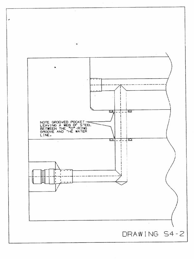
13) “O”-rings must be designed with a grooved pocket to completely retain the “O”-ring
(Refer to drawing S4-2).
Industrial Standard groove diameters and depths will be used such as supplied through PARCO, Standard Die,
etc. (usually available through “O”-ring supplier)

Injection Mold slide lifter standards
Injection Mold runner standards
Injection Mold cooling standards
Injection Mold venting standards
Injection Mold Ejector System standards standards
Injection Mold component standards
Injection Mold Hydraulic and Pneumatic standards
Injection Mold Design Check standards
Injection Mold Steel Grades standards
Injection Mold inspection standards