
Definition
Unbalanced flow is plastic completely filling some flow paths in the mold before other flow paths have
filled.
Unbalanced flow
Unbalanced flow can be the cause of many molding problems such as flashing, short shots, high cycle
time, density differences throughout the part, warpage, air traps and extra weld lines.
Flow is balanced when all the extremities of the mold fill at the same time.
To recognize unbalanced flow, you need to recognize the different flow paths in the mold. These are the different
routes that the plastic takes throughout the cavity.
The following part contains three fundamental flow paths (shown as red arrows).
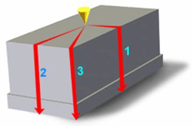
Each flow path is of a different length. Therefore, if the part has uniform thickness, flow path 1 will fill first,
followed by flow path 2, followed by flow path 3.
The key result used to identify unbalanced flow is the fill time result.
What to do
By altering the thickness of regions within the part, flow can be hastened or delayed in certain
directions to help balance flows. In the above diagram, varying the part thickness and creating flow leaders and deflectors,
thinning flow path 1 and thickening flow path 3, is the answer. These variations in thickness are known as Flow Leaders or
Flow Deflectors.
In other examples it is often necessary to consider the position of the polymer injection location, or the number
of polymer injection locations. For example, if you choose a single injection location that defines some flow paths to be three
or four times the length of others, then it is almost impossible to balance flows. Try moving the polymer injection location to
a position that will define similar length flow paths. Alternatively, visualize the cavity in smaller, more manageable sections.
Then use multiple injection locations, one per sub-section.
For a multi-cavity part, balance flows in each cavity first, then proceed to alter runner dimensions
to ensure that:
All cavities fill at approximately the same time, with the same pressure
The temperature at the end of fill shows uniform distribution in each cavity, predicting uniform
shrinkage, and acceptable weld line quality.
The shear stress in each cavity (ignore runners) is less than the recommended limit for the material
chosen.
Injection Molding air trap issue and solution
Injection Molding brittleness issue and solution
Injection Molding burn issue and solution
Injection Molding crack issue and solution
Injection Molding delamination issue and solution
Injection Molding dimensional variation issue and solution
Injection Molding discoloration issue and solution
Injection Molding excessive part weight issue and solution
Injection Molding fish eye issue and solution
Injection Molding flash issue and solution
Injection Molding follow line issue and solution
Injection Molding hesitation issue and solution
Injection Molding high volumetric shrinkage issue and solution
Injection Molding jetting issue and solution
Injection Molding overpacking issue and solution
Injection Molding racetrack effect issue and solution
Injection Molding short shot issue and solution
Injection Molding sink mark and void issue and solution
Injection Molding unbalanced flow issue and solution
Injection Molding underflow issue and solution
Injection Molding warpage issue and solution
Injection Molding weld and meld line issue and solution