
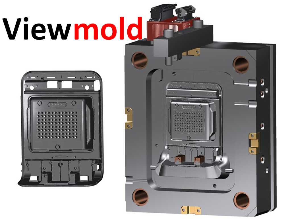
Injection mold tooling design services
Viewmold company provides professional plastic injection mold tool design services as DME or HASCO standard for customers in full 3D formats from your 2D or 3D CAD files. Our company's design services team have 10 employees, and have 6 senior injection mold tooling engineers. Our
engineers can design injection molds from basic single cavity prototype to complex, multi-cavity long life production molds.
Our designer also can create a comlex part 3D from your actual sample. Please contact us:
sales@viewmold.com or submit a quote online..
Our design department can support multiple file formats from our customers. Our powerful Unigraghics CAD system transforms your part data into a precision 3-D solid modeled for mold design. We can also create a complete 3D model of your intended part or convert your 2-D drawings to a 3-D solid CAD model. We can review your CAD files or part drawings, help ensure your product can be manufactured and provide feedback on possible quality issues or areas in need of improvement. If we find an area in your part design that can not physically be manufactured or has quality issues, we will make a modification to your 3-D CAD model with a solution that best fits the application and return it to you for approval. We utilize Moldflow to analysis the products and simulate injection molding processes to avoid potential process defects (such as: sink, warpage), enable you to predict and solve process problems in the earliest stage. We believe that a quality injection molding tooling comes from a quality injection mold design.
The following is our services
Part design service
1:From 2D to 3D part model.2:From actual sample or prototype to 3D part model.
Part modification services
Our engineers use NX software its part design function is very strong, we can do any modification for part design from your request. Part design check services
The part design check is very important, unreasonable part will cause more injection mold defects.1:Thickness check, uneven wall thickness will cause some injection molding issues.
Thicker thickness of part will cause molding sink mark and void. Thinner thickness of part will cause molding short shot. Our engineers will check thickness of the part design, the check includes all area of the part. We'll provide thickness information photo to our customers.
2:Draft angle check, No draft or less draft angle will cause scratch or part will stay in the stationary side. Our design team will check all draft of the part.
3: Warpage risk estimating, warpage is trouble issue, the serious will cause failure of part. Unreasonable part design will add warpage risk. Our injection mold design team research warpage for 10 years, and have rich experience for the issue. Our design engineer will estimate the warpage risk of each part each, and provide relative information to our customer.
How to design suitable part for injection molding? The following information is some major guidelines that can be summed up in just a few design rules.
1 Injection molding design better uses uniform wall thicknesses throughout the part. This will minimize sinking, warping, Sink Marks is the plastic solidifies in the mold it freezes from the outside (near the mold surface) toward the inside. In thick sections this results in inward pulling stresses (due to contraction) that can cause sink marks in the outer surfaces of the part. Thicker and non-uniform wall thicknesses can often result in sinks in the material due to the same solidification physics described above.
2 The part design by injection molding better uses generous radius at all corners. The inside corner radius should be a minimum of one material thickness.
3 The part design by injection molding better uses the thinner thickness compliant with the process, material, or product design requirements. Using the thinner wall thickness for the process ensures rapid cooling, short cycle times, and minimum shot weight. All these result in the least possible part cost.
4 Design parts of the injection molding to facilitate easy withdrawal from the mold by providing draft (taper) in the direction of mold opening or closing.
6 Injection molding part design better uses ribs or gussets to improve part stiffness in bending. This avoids the use of thick section to achieve the same, thereby saving on part weight, material costs, and cycle time costs. Rib-to-wall thickness ratios: Thin ribs on thicker walls may provide stiffness but also can result in sinking on the outside of the wall. This rule-of-thumb guideline should help keep this from happening Watch rib-to-wall thickness ratios prevent sink, the thickness of the rib should be about 0.7 of the thickness of the wall.
Here are some general injection molding part design guidelines to help you for learning the injection molding design, but for perfect products, you have to learn more and practice more in your work. You also can contact us, our injection mold tooling design engineers will provide you more professional injection molding part design suggestions.
Moldflow services
Our design department will do moldflow analysis before starting injection mold design. It can avoid potential
injection mold defects risk.injection mold tooling design
 Our design department will provide 3D injection mold design, the 3D design will include all compoents in the tooling, each screw, each ejector pin...
3D injection mold design Include:
All components, actions, and blocks in Solid Model format. The data will represent the actual steel conditions insofar as possible
all vents, vent clearances, and parting line clearances
any sub-inserts required for in-process ECNs and/or corrections (NOTE: Design data must reflect steel conditions insofar as possible)
Engraving information
All Hot Runner/Nozzle components, including electrical connector pockets/junction boxes, etc.
All hydraulic cylinders. NOTE: Complex hydraulic plumbing should be modeled as needed
All lifting holes, brackets, lifting straps, safety straps, protecting pillars
Water manifolds if required
Press platen and tie bars
mold design check
After the mold design is finished, our manager of injection mold design department will check carefully it according our
injection mold design check standard.BOM sheet services
Our mold design team will provides Bill Of Material sheet for each injection molding tooling.
BOM sheet includes each standard mold compoents type, quantity, also include other components size, material.2D drawing services
Before you start maufacturing the injection mold tooling, our design team will provide you 2d drawing, it includes all position dimensions fo ejetor holes, waterlines and screws.
Final drawing 2-D Mold design include:Over-all dimensions (length, width, mold stack height, stroke, plate thickness. Etc.).
mold designated
Views to clarify actions, water layout, and special features
views as required (Example: 3-Plate molds, Floating cores, etc.)
Enlarged view of gate(s) with dimensions
Steel types and hardness
Watts, Volts, Amps per zone, Hot Runner information
Power and Thermocouple connectors/junction box
General Notes and tolerances, Texturing information, special sequencing notes, paint requirements, coating/plating requirements, etc.
Material List to include quantity required, detail number, over-all dimensions, catalog number, material type, and supplier (Standard Viewmold format)
Water and hydraulic connector information noted.
Water and hydraulic thread sizes noted.
Eyebolt sizes noted.
Completed title block with material and shrink, press size and model, etc.
Press tie bars shown in plan views
Detail views and dimensions as required. We will maintain the "data-driven" approach unless otherwise specified by the customer and compensated appropriately.
injection mold design Description
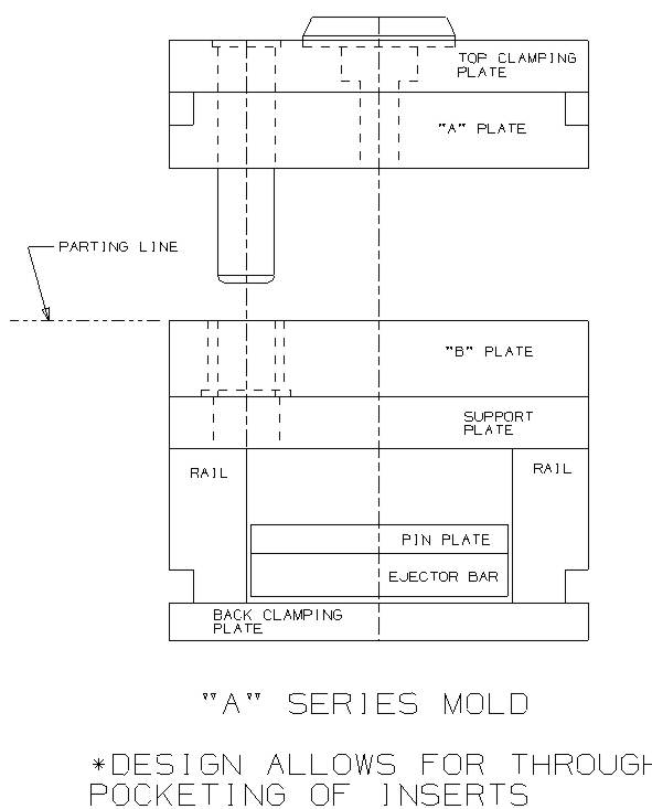
Section 1: Moldbase Series Description
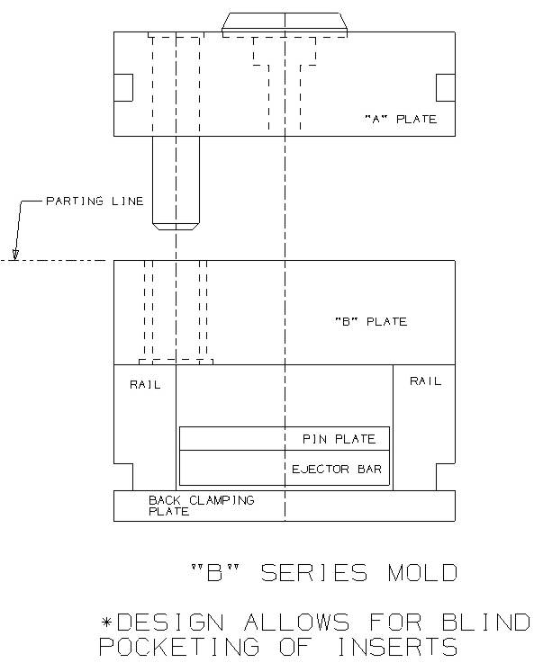
"A"Series Mold: Design allows for through pocketing of inserts (refer to drawing S1-1)"B"Series Mold: Design allows for blind pocketing of inserts and solid,core/cavity (refer to drawing S1-2)
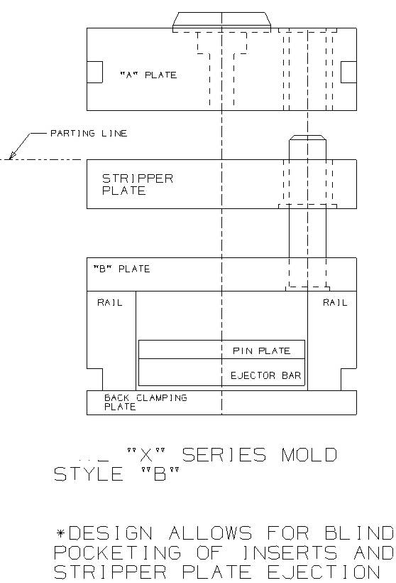
 "X"Series Mold: Design allows for through pocketing of inserts and stripper plate ejection (refer to drawing S1-3). design allows
for blind pocketing of inserts and stripper plate ejection (refer to drawing S1-4)
"X"Series Mold: Design allows for through pocketing of inserts and stripper plate ejection (refer to drawing S1-3). design allows
for blind pocketing of inserts and stripper plate ejection (refer to drawing S1-4)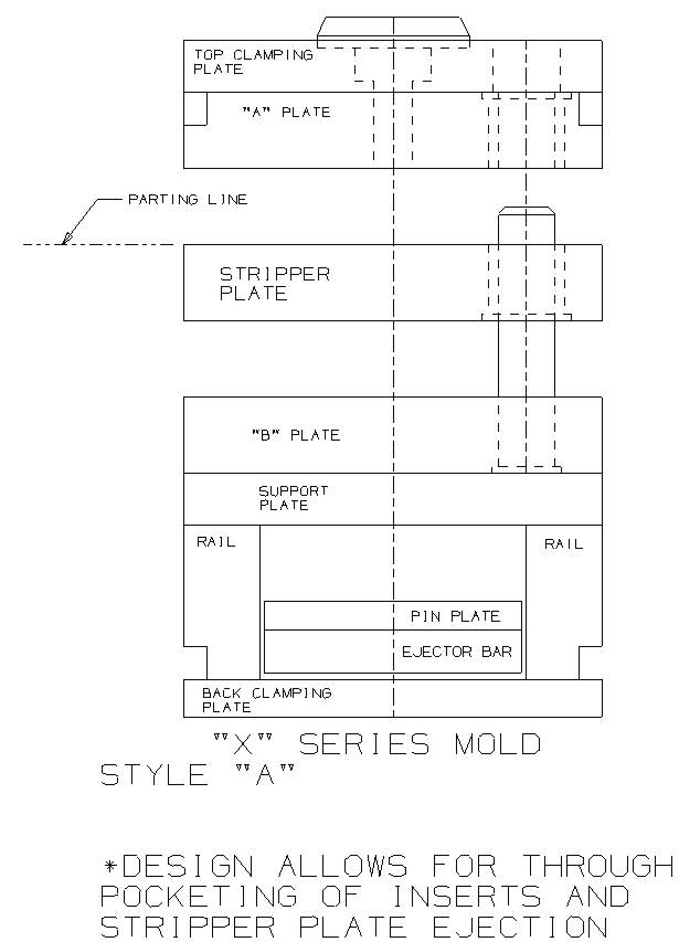
 "AX"Series Mold: Design allows for cavity floating plate action (refer to drawing S1-5)
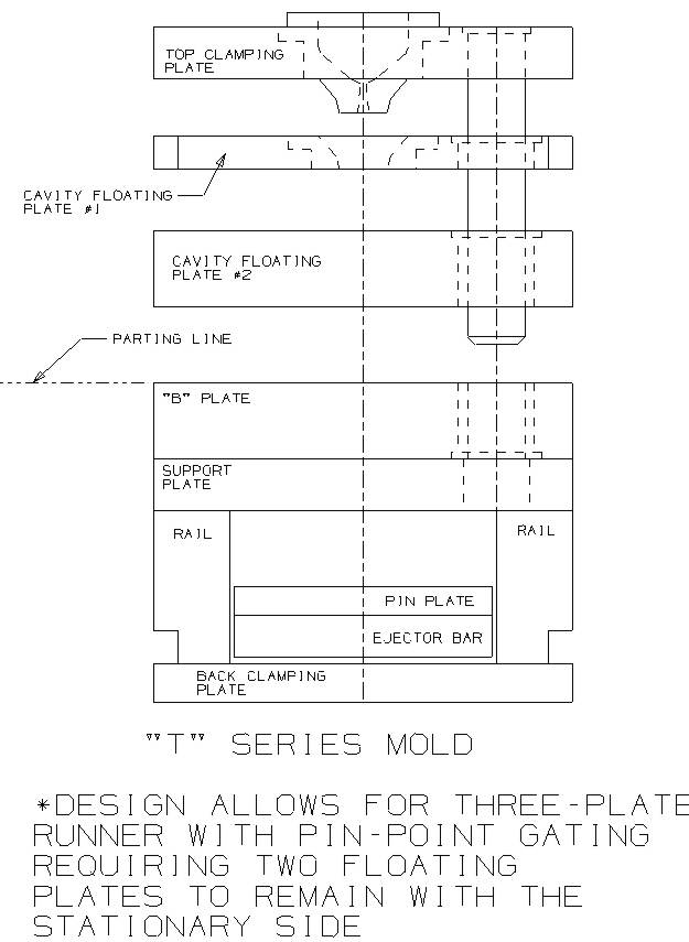
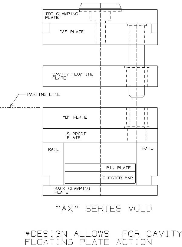 "T"Series Mold: Design allows for three-plate runner with pin point gating requiring two floating plates to remain with the stationary
side (refer to drawing S1-6)
"T"Series Mold: Design allows for three-plate runner with pin point gating requiring two floating plates to remain with the stationary
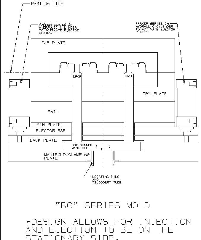
side (refer to drawing S1-6)"RG"Series Mold: Design allows for injection and ejection to be on the stationary side (refer to drawing S1-7)
Section 2: mold Slides/Lifters/Actions Standards and Design
Contents:A) Mechanical Slide Design Standards
B) Hydraulic Slide Design Standards
C) Lifter Design Standards
Section 3: Runner System Standards and Design
Contents:
A) Surface Runner and gate Design Standards
B) Hot Runner Design Guidelines
C) Three plate runner and Pin-Point Gate Design Standards
Section 4: injection mold Cooling Standards and Design
Defines methods to provide optimum mold temperature control
Section 5: injection mold Venting Standards and Design
Section 6: injection mold Ejector System Standards and Design
Contents:A) Ejector pin design standards
B) Guided ejection design standards
C) Spring return standards
D) Hydraulic ejector standards
E) Press Knock-out (PKO) design standards
Section 7: Standard Components
Defines standard component types and suppliersSection 8: Hydraulic and Pneumatic Standards and Design
Contents:a) Hydraulic Standards
b) Pneumatic Standards