
ViewMold Co Ltd is an ISO 9001:2000 certified plastic injection molds company that supplies
plastic injection molds
plastic injection molds design
plastic injection molds manufacturing of high quality,plastic injection molding...
We are Proud to bring to you the quality and speed you would expect from Viewmold plastic injection molds. We believe we will be your supplier of choice. Just give Viewmold a
email or
submit a quote online.
Our team of quote specialists is the most responsive and the most hands on.
TIGHTENING TORQUES AND THE
TORQUE-TENSION RELATIONSHIP
All of the analysis and design work done in advance will have little meaning if the proper preload is not achieved. Several discussions in this technical section stress the importance of preload to maintaining joint integrity. There are many methods for measuring preload (see Table 12). However, one of the least expensive techniques that provides a reasonable level of accuracy versus cost is by measuring torque. The fundamental characteristic required is to know the relationship between torque and tension for any particular bolted joint. Once the desired design preload must be identified and specified first, then the torque required to induce that preload is determined.
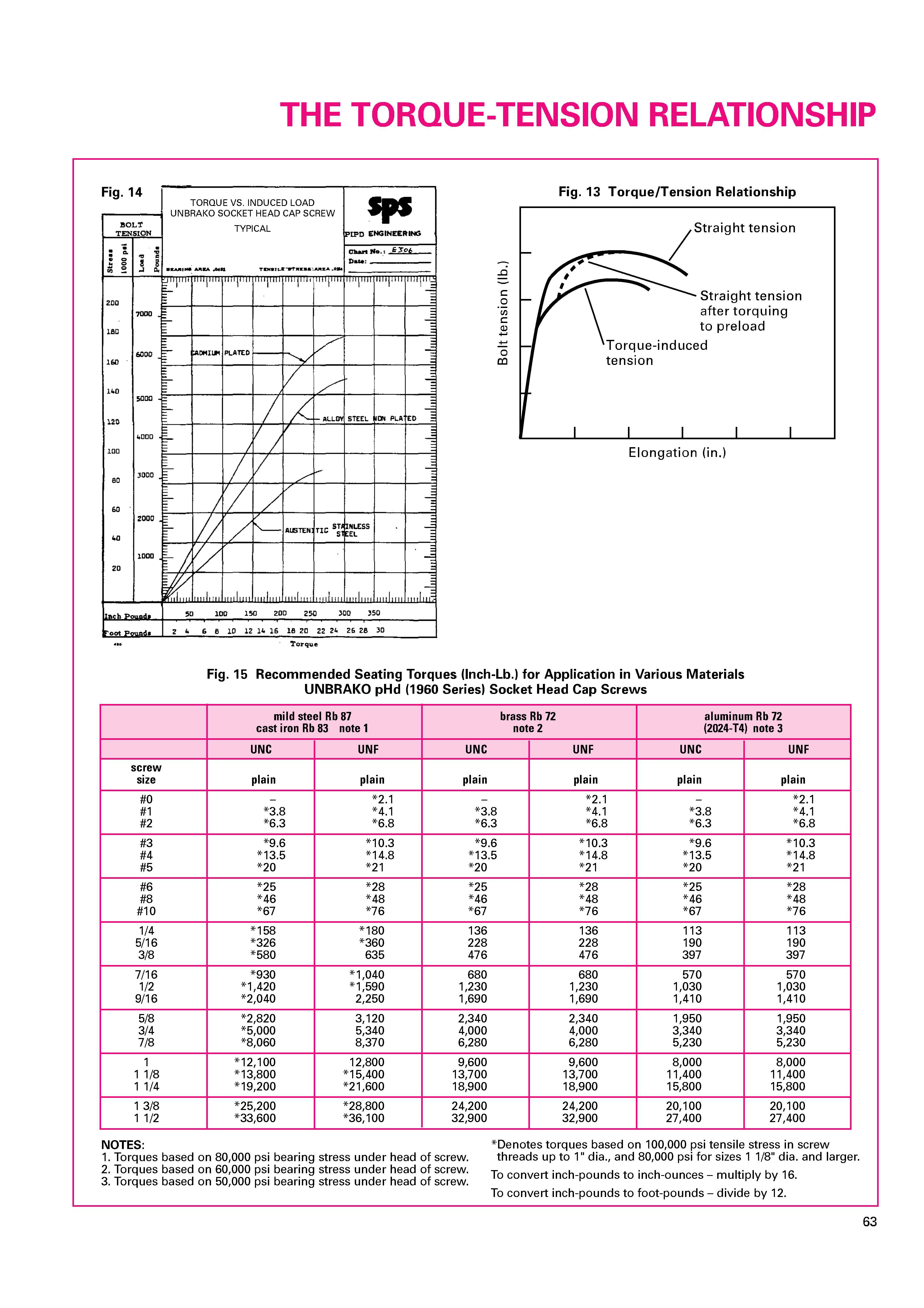
Within the elastic range, before permanent stretch is induced, the relationship between torque and tension is essentially linear (see figure 13). Some studies have found up to 75 variables have an effect on this relationship: materials, temperature, rate of installation, thread helix angle, coefficients of friction, etc. One way that has been developed to reduce the complexity is to depend on empirical test results. That is, to perform experiments under the application conditions by measuring the induced torque and recording the resulting tension. This can be done with relatively simple, calibrated hydraulic pressure sensors, electric strain gages, or piezoelectric load cells. Once the data is gathered and plotted on a chart, the slope of the curve can be used to calculate a correlation factor. This technique has created an accepted formula for relating torque to tension.
T = K X D X P
T = torque, lbf.-in.
D = fastener nominal diameter, inches
P = preload, lbf.
K = "nut factor", or"tightening factor", or "k-value"
If the preload and fastener diameter are selected in
the design process, and the K-value for the application
conditions is known, then the necessary torque can be
calculated. It is noted that even with a specified torque,
actual conditions at the time of installation can result in
variations in the actual preload achieved (see Table 12).
One of the most critical criteria is the selection of the
K-value. Accepted nominal values for many industrial
applications are:
K = 0.20 for as-received steel bolts into steel holes
K = 0.15 steel bolts with cadmium plating, which acts like
a lubricant,
K = 0.28 steel bolts with zinc plating.
The K-value is not the coefficient of the friction (); it is
an empirically derived correlation factor.
It is readily apparent that if the torque intended for a
zinc plated fastener is used for cadmium plated fastener,
the preload will be almost two times that intended; it
may actually cause the bolt to break.
Another influence is where friction occurs. For steel
bolts holes, approximately 50% of the installation torque
is consumed by friction under the head, 35% by thread
friction, and only the remaining 15% inducing preload
tension. Therefore, if lubricant is applied just on the
fastener underhead, full friction reduction will not be
achieved. Similarly, if the material against which the
fastener is bearing, e.g. aluminum, is different than the
internal thread material, e.g. cast iron, the effective
friction may be difficult to predict, These examples
illustrate the importance and the value of identifying
the torque-tension relationship. It is a recommend
practice to contact the lubricant manufacturer for
K-value information if a lubricant will be used.
The recommended seating torques for Unbrako
headed socket screws are based on inducing preloads
reasonably expected in practice for each type. The
values for Unbrako metric fasteners are calculated
using VDI2230, a complex method utilized extensively
in Europe. All values assume use in the received con-
dition in steel holes. It is understandable the designer
may need preloads higher than those listed. The
following discussion is presented for those cases.
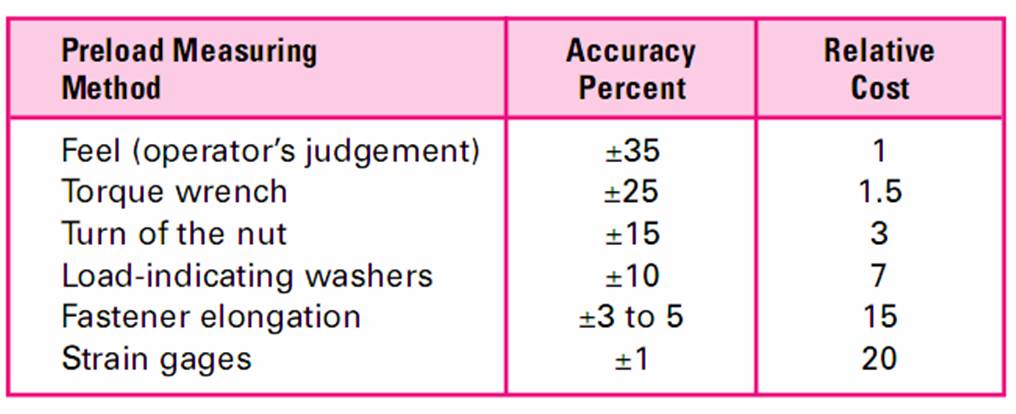
Table 12
Industrial Fasteners Institute's
Torque-Measuring Method
TORSION-TENSION YIELD AND TENSION
CAPABILITY AFTER TORQUING
Once a headed fastener has been seated against a bear-
ing surface, the inducement of torque will be translated
into both torsion and tension stresses. These stresses
combine to induce twist. If torque continues to be induced,
the stress along the angle of twist will be the largest
stress while the bolt is being torqued. Consequently, the
stress along the bolt axis (axial tension) will be something
less. This is why a bolt can fail at a lower tensile stress
during installation than when it is pulled in straight tension
alone, eg . a tensile test. Research has indicated the axial
tension can range from 135,000 to 145,000 PSI for industry
socket head cap screws at torsion-tension yield, depending on diameter. Including the preload variation that can
occur with various installation techniques, eg. up to 25%,
it can be understood why some recommended torques
induce preload reasonably lower than the yield point.
Figure 13 also illustrates the effect of straight tension
applied after installation has stopped. Immediately after
stopping the installation procedure there will be some
relaxation, and the torsion component will drop toward
zero. This leaves only the axial tension, which keeps
the joint clamped together. Once the torsion is relieved,
the axial tension yield value and ultimate value for the
fastener will be appropriate.