

INSTALLATION CONTROL
Several factors should be considered in designing a joint or selecting a fastener for a particular application.JOINT DESIGN AND FASTENER SELECTION.
Joint Length.
The longer the joint length, the greater the total elongation will occurin the bolt to produce the desired clamp
load or preload. In design, if the joint length is increased, the potential loss of preload is decreased.Joint Material
If the joint material is relatively stiff compared to the bolt material, it will compress less and therefore provide a
less sensitive joint, less sensitive to loss of preload as a result of brinelling, relaxation and even loosening.Thread Stripping Strength
Considering the material in which the threads will be
tapped or the nut used, there must be sufficient engagement length to carry the load. Ideally, the length of
thread engagement should be sufficient to break the
fastener in tension. When a nut is used, the wall thickness of the nut as well as its length must be considered.An estimate, a calculation or joint evaluation will be required to determine the tension loads to which the bolt and joint will be exposed. The size bolt and the number necessary to carry the load expected, along with the safety factor, must also be selected.
The safety factor selected will have to take into con- sideration the consequence of failure as well as the addi- tional holes and fasteners. Safety factors, therefore, have to be determined by the designer.
SHEAR APPLICATIONS
Shear Strength of Material
Not all applications apply a tensile load to the fastener. In
many cases, the load is perpendicular to the fastener in
shear. Shear loading may be single, double or multiple
loading.There is a relationship between the tensile strength of a material and its shear strength. For alloy steel, the shear strength is 60% of its tensile strength. Corrosion resistant steels (e.g. 300-Series stainless steels) have a lower tensile/shear relationship and it is usually 50-55%
Single/Double Shear
Single shear strength is exactly one-half the double shear
value. Shear strength listed in pounds per square inch
(psi) is the shear load in pounds multiplied by the cross
sectional area in square inches.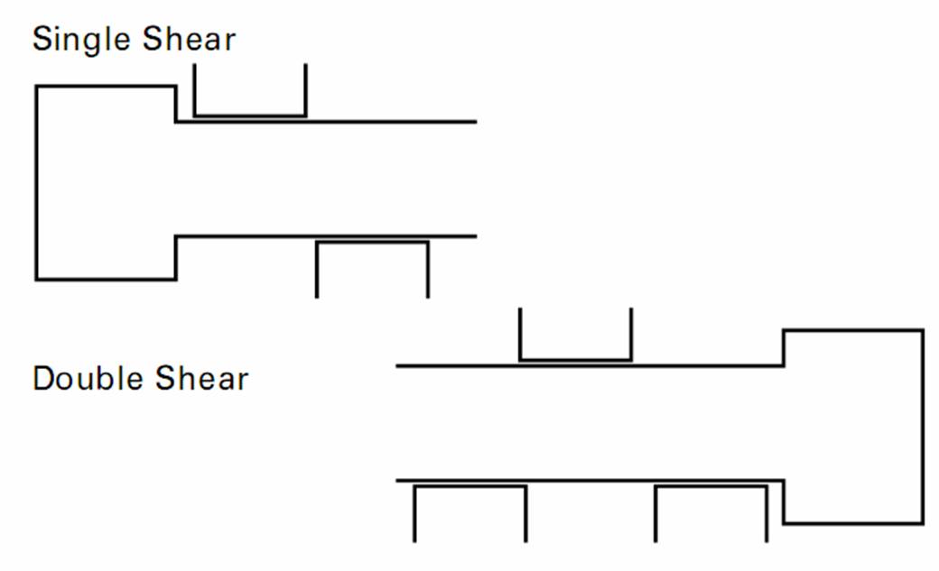
OTHER DESIGN CONSIDERATIONS
Application Temperature
For elevated temperature, standard alloy steels are useful
to about 550-C600. However, if plating is used,
maximum temperature may be less (eg. cadmium
should not be used over 450
Austenitic stainless steels (300 Series) may be useful
to 800. They can maintain strength above 800 but wi
begin to oxidize on the surface.Corrosion Environment
A plating may be selected for mild atmospheres or salts.
If plating is unsatisfactory, a corrosion resistant fastener
may be specified. The proper selection will be based
upon the severity of the corrosive environment.FATIGUE STRENGTH
S/N Curve
Most comparative fatigue testing and specification
fatigue test requirements are plotted on an S/N curve.
In this curve, the test stress is shown on the ordinate
(y-axis) and the number of cycles is shown on the
abscissa (x-axis) in a lograthmic scale. On this type
curve, the high load to low load ratio must be shown.
This is usually R =.1, which means the low load in all
tests will be 10% of the high load. 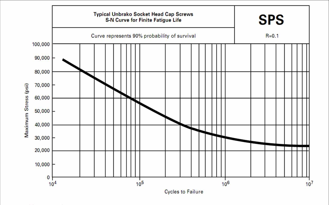
Effect of Preload
Increasing the R to .2, .3 or higher will change the curve shape. At some point in this curve, the number of cycles will reach 10 million cycles. This is considered the endurance limit or the stress at which infinite life might be expected.
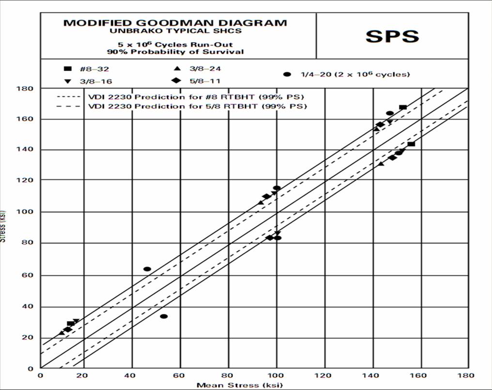
Modified Goodman/ Haigh Soderberg Curve
The S/N curve and the information it supplies will not provide the information needed to determine how an individual fastener will perform in an actual application. In application, the preload should be higher than any of the preloads on the S/N curve. Therefore, for application information, the modified Goodman Diagram and/or the Haigh Soderberg Curve are more useful. These curves will show what fatigue performance can be expected when the parts are properly preloaded.
Mean Stress (ksi) METHODS OF PRELOADING
Elongation
The modulus for steel of 30,000,000 (thirty million) psi
means that a fastener will elongate .001 in/in of length
for every 30,000 psi in applied stress. Therefore, if 90,000
psi is the desired preload, the bolt must be stretched .003
inches for every inch of length in the joint.This method of preloading is very accurate but it requires that the ends of the bolts be properly prepared and also that all measurements be very carefully made. In addition, direct measurements are only possible where both ends of the fastener are available for measurement after installation. Other methods of measuring length changes are ultrasonic, strain gages and turn of the nut.
Torque
By far, the most popular method of preloading is by
torque. Fastener manufacturers usually have recommended seating torques for each size and material
fastener. The only requirement is the proper size
torque wrench, a conscientious operator and the
proper torque requirement.Strain
Since stress/strain is a constant relationship for any
given material, we can use that relationship just as the
elongation change measurements were used previously.
Now, however, the strain can be detected from strain
gages applied directly to the outside surface of the bolt
or by having a hole drilled in the center of the bolt and
the strain gage installed internally. The output from these
gages need instrumentation to convert the gage electrical
measurement method. It is, however, an expensive
method and not always practical. Turn of the Nut
The nut turn method also utilizes change in bolt length.
In theory, one bolt revolution (360?rotation) shoul
increase the bolt length by the thread pitch. There are
at least two variables, however, which influence this
relationship. First, until a snug joint is obtained, no bolt
elongation can be measured. The snugging produces a
large variation in preload. Second, joint compression is
also taking place so the relative stiffnesses of the joint
and bolt influences the load obtained.VARIABLES IN TORQUE
Coefficient of Friction
Since the torque applied to a fastener must overcome
all friction before any loading takes place, the amount of
friction present is important.In a standard unlubricated assembly, the friction to be overcome is the head bearing area and the thread-to- thread friction. Approximately 50% of the torque applied will be used to overcome this head-bearing friction and approximately 35% to overcome the thread friction. So 85% of the torque is overcoming friction and only 15% is available to produce bolt load.
If these interfaces are lubricated (cadmium plate, molybdenum disulfide, anti-seize compounds, etc.), the friction is reduced and thus greater preload is produced with the same torque.
The change in the coefficient of friction for different conditions can have a very significant effect on the slope of the torque tension curve. If this is not taken into consideration, the proper torque specified for a plain unlubricated bolt may be sufficient to yield or break a lubricated fastener.
Thread Pitch
The thread pitch must be considered when a given stress
is to be applied, since the cross-sectional area used for
stress calculations is the thread tensile stress area and is
different for coarse and fine threads. The torque recommendations, therefore, are slightly higher for fine threads
than for coarse threads to achieve the same stress.Differences between coarse and fine threads.
Coarse Threads are...
more readily available in industrial fasteners.
easier to assemble because of larger helix angle.
require fewer turns and reduce cross threading.
higher thread stripping strength per given length.
less critical of tap drill size.
not as easily damaged in handling.
Their disadvantages are...
lower tensile strength.
reduced vibrational resistance.coarse adjustment.
Fine Threads provide...
higher tensile strength.
greater vibrational resistance.
finer adjustment.
Their disadvantages are...
easier cross threaded.
threads damaged more easily by handling.
tap drill size slightly more critical.
slightly lower thread stripping strength.
Other Design Guidelines
In addition to the joint design factors discussed, the
following considerations are important to the proper use
of high-strength fasteners.Adequate thread engagement should be guaranteed by use of the proper mating nut height for the system. Minimum length of engagement recommended in a tapped hole depends on the strength of the material, but in all cases should be adequate to prevent stripping.
Specify nut of proper strength level. The bolt and nut should be selected as a system.
Specify compatible mating female threads. 2B tapped holes or 3B nuts are possibilities.
Corrosion, in general, is a problem of the joint, and not just of the bolt alone. This can be a matter of galvanic action between dissimilar metals. Corrosion of the fastener material surrounding the bolt head or nut can be critical with high-strength bolting. Care must be exercised in the compatibility of joint materials and/or coatings to protect dissimilar metals.
PROCESSING CONTROL
The quality of the raw material and the processing
control will largely affect the mechanical properties of
the finished parts.MATERIAL SELECTION
The selection of the type of material will depend on its
end use. However, the control of the analysis and quality
is a critical factor in fastener performance. The material
must yield reliable parts with few hidden defects such as
cracks, seams, decarburization and internal flaws.FABRICATION METHOD
Head
There are two general methods of making bolt heads,
forging and machining. The economy and grain flow
resulting from forging make it the preferred method.The temperature of forging can vary from room temperature to 2000?F. By far, the greatest number o parts are cold upset on forging machines known as headers or boltmakers. For materials that do not have enough formability for cold forging, hot forging is used. Hot forging is also used for bolts too large for cold upsetting due to machine capacity. The largest cold forging machines can make bolts up to 1-1/2 inch diameter. For large quantities of bolts, hot forging is more expensive then cold forging.
Some materials, such as stainless steel, are warm forged at temperatures up to 1000?F. The heating result in two benefits, lower forging pressures due to lower yield strength and reduced work hardening rates. Machining is the oldest method and is used for very large diameters or small production runs.
The disadvantage is that machining cuts the metal grain flow, thus creating planes of weakness at the critical head-to-shank fillet area. This can reduce tension fatigue performance by providing fracture planes.
Fillets
The head-to-shank transition (fillet) represents a sizable
change in cross section at a critical area of bolt perfor-
mance. It is important that this notch effect be minimized. A generous radius in the fillet reduces the notch
effect. However, a compromise is necessary because too
large a radius will reduce load-bearing area under the
head.Composite radii such as elliptical fillets, maximize curvature on the shank side of the fillet and minimize it on the head side to reduce loss of bearing area on the load-bearing surface.
Critical Fastener Features
Threads can be produced by grinding, cutting or rolling.
In a rolled thread, the material is caused to flow into
the thread die contour, which is ground into the surface
during the manufacture of the die. Machines with two or
three circular dies or two flat dies are most common.Thread cutting requires the least tooling costs and is by far the most popular for producing internal threads. It is the most practical method for producing thin wall parts and the only technique available for producing large diameter parts (over 3 inches in diameter).
Thread grinding yields high dimensional precision and affords good control of form and finish. It is the only practical method for producing thread plug gages.
Both machining and grinding have the disadvantage of cutting material fibers at the most critical point of performance.
 The shape or contour of the thread has a great effect
on the resulting fatigue life. The thread root should be
large and well rounded without sharp corners or stress
risers. Threads with larger roots should always be used
for harder materials.
The shape or contour of the thread has a great effect
on the resulting fatigue life. The thread root should be
large and well rounded without sharp corners or stress
risers. Threads with larger roots should always be used
for harder materials.In addition to the benefits of grain flow and controlled shape in thread rolling, added fatigue life can result when the rolling is performed after heat treatment. This is the accepted practice for high fatigue performance bolts such as those used in aircraft and space applications.
EVALUATING PERFORMANCE
Mechanical Testing
In the fastener industy, a system of tests and examina-
tions has evolved which yields reliable parts with proven
performance.Some tests are conducted on the raw material; some on the finished product.
There always seems to be some confusion regarding mechanical versus metallurgical properties. Mechanical properties are those associated with elastic or inelastic reaction when force is applied, or that involve the relationship between stress and strain. Tensile testing stresses the fastener in the axial direction. The force at which the fastener breaks is called the breaking load or ultimate tensile strength. Load is designated in pounds, stress in pounds per square inch and strain in inches per inch.
When a smooth tensile specimen is tested, the chart obtained is called a Stress-Strain Curve. From this curve, we can obtain other useful data such as yield strength. The method of determining yield is known as the offset method and consists of drawing a straight line parallel to the stress strain curve but offset from the zero point by a specified amount. This value is usually 0.2% on the strain ordinate. The yield point is the intersection of the stressstrain curve and the straight line. This method is not applicable to fasteners because of the variables introduced by their geomety.
When a fastener tensile test is plotted, a load/ elongation curve can be obtained. From this curve, a yield determination known as Johnson's 2/3 approximat method for determination of yield strength is used to establish fastener yield, which will be acceptable for design purposes. It is not recommended for quality control or specification requirements.
Torque-tension testing is conducted to correlate the required torque necessary to induce a given load in a mechanically fastened joint. It can be performed by hand or machine. The load may be measured by a tensile machine, a load cell, a hydraulic tensile indicator or by a strain gage.
Fatigue tests on threaded fasteners are usually alter- nating tension-tension loading. Most testing is done at more severe strain than its designed service load but ususally below the material yield strength.
Shear testing, as previously mentioned, consists of loading a fastener perpendicular to its axis. All shear testing should be accomplished on the unthreaded portion of the fastener.
Checking hardness of parts is an indirect method for testing tensile strength. Over the years, a correlation of tensile strength to hardness has been obtained for most materials. See page 83 for more detailed information. Since hardness is a relatively easy and inexpensive test, it makes a good inspection check. In hardness checking, it is very important that the specimen be properly pre- pared and the proper test applied.
Stress durability is used to test parts which have been subjected to any processing which may have an embrittling effect. It requires loading the parts to a value higher than the expected service load and maintaining that load for a specified time after which the load is removed and the fastener examined for the presence of cracks.
Impact testing has been useful in determining the ductile brittle transformation point for many materials. However, because the impact loading direction is transverse to a fastener's normal longitude loading, its usefulness for fastener testing is minimal. It has been shown that many fastener tension impact strengths do not follow the same pattern or relationship of Charpy or Izod impact strength.
Metallurgical Testing
Metallurgical testing includes chemical composition,
microstructure, grain size, carburization and decarburization, and heat treat response.The chemical composition is established when the material is melted. Nothing subsequent to that process will influence the basic composition.
The microstructure and grain size can be influenced by heat treatment. Carburization is the addition of carbon to the surface which increases hardness. It can occur if heat treat furnace atmospheres are not adequately controlled. Decarburization is the loss of carbon from the surface, making it softer. Partial decarburization is preferable to carburization, and most industrial standards allow it within limits.
In summary, in order to prevent service failures, many things must be considered:
The Application Requirements
Strength Needed - Safety FactorTension/Shear/Fatigue
Temperature
Corrosion
Proper Preload
The Fastener Requirements
MaterialFabrication Controls
Performance Evaluations