Determining Metric Tolerances
Table 1: Description of PreferredFits
Table 1 is pulled from the ANSI metric tolerances section of thee machinists handbook, which conforms to the ISO and DIN toleances for hole
basis and shaft basis fits. Table 1 provides an overview of the hole basis and shaft basis fits that make up clearance fit,
transition fit and interference fit combinations..
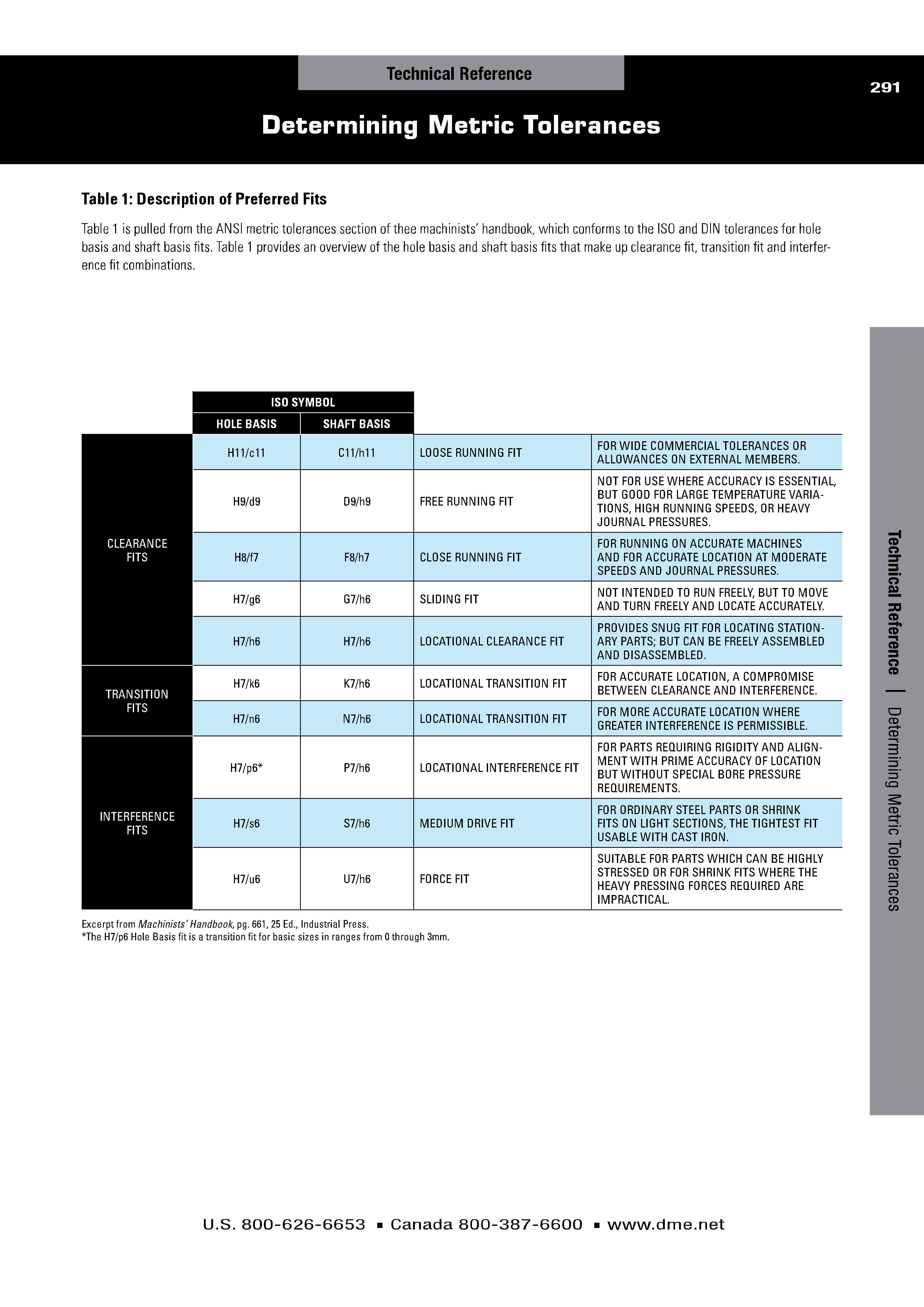
Table 2: Commonly used Hole-BasisSystem of fits
Table 2 shows closer detail on the hole-basis system of ?ts than Table 1. When using the hole-basis system of fits, the smallest diameter in the
hole tolerance range is ?xed to the zero line (basic nominal hole size or diameter), and the clearance between the shaft and hole extends below
the zero line, or negative relative to the basic nominal hole size.Table 3: Commonly used Shaft-BasisSystem of fits
Table 3 shows closer detail on the shaft-basis system of ?ts than Table 1. When using the shaft-basis system of ?ts, the largest diameter in the
shaft tolerance range is ?xed to the zero line (basic nominal shaft size or diameter), and the clearance between the shaft and hole extends above
the zero line, or positive relative to the basic shaft size.
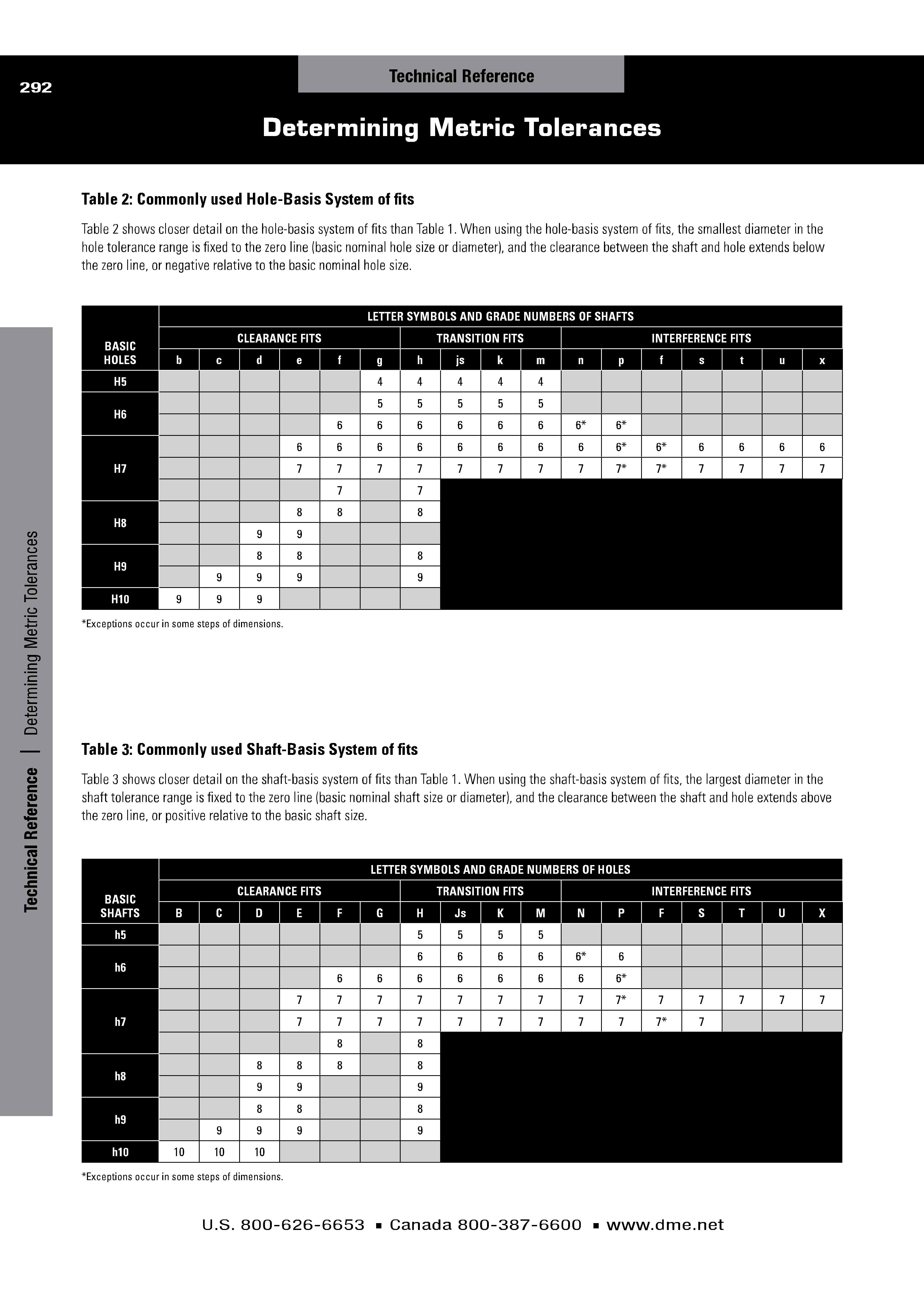
Table 4: ITStandard Tolerances
Table 4 details the ISO-basic tolerances (International Tolerance Grades, which apply to all linear sizes (externalnd internal sizes, diam-
eters, lengths, widths and thicknesses). An IT-grade number establishes the magnitude of the tolerance zone, while the tolerance position letter
determines where the tolerance zone is in relation to the zero line. The combination of tolerance position letter (A-X, a-x) and IT-grade number
(01-8) creates the overall tolerance symbol (i.e., F8/h7 when using the shaft-basis system of ?ts).For nominal size range up to 500mm according to DIN 7151/ISO 286, and for nominal size range over 500mm, according to DIN 7172/ISO 286.
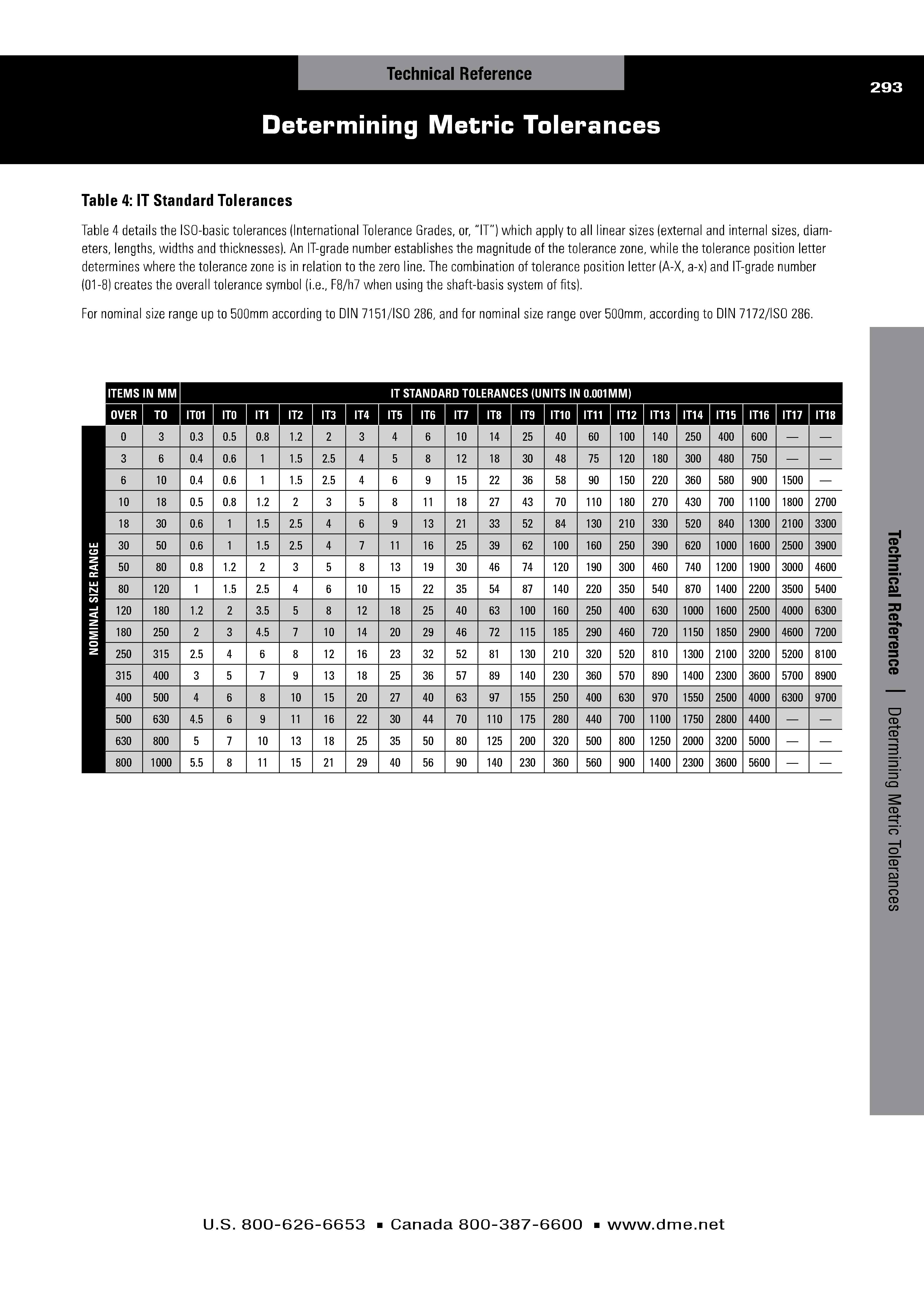
Table 5: Fundamental deviations of holes and shafts
Table 5 details fundamental deviations between holes and shafts, and is provided for reference.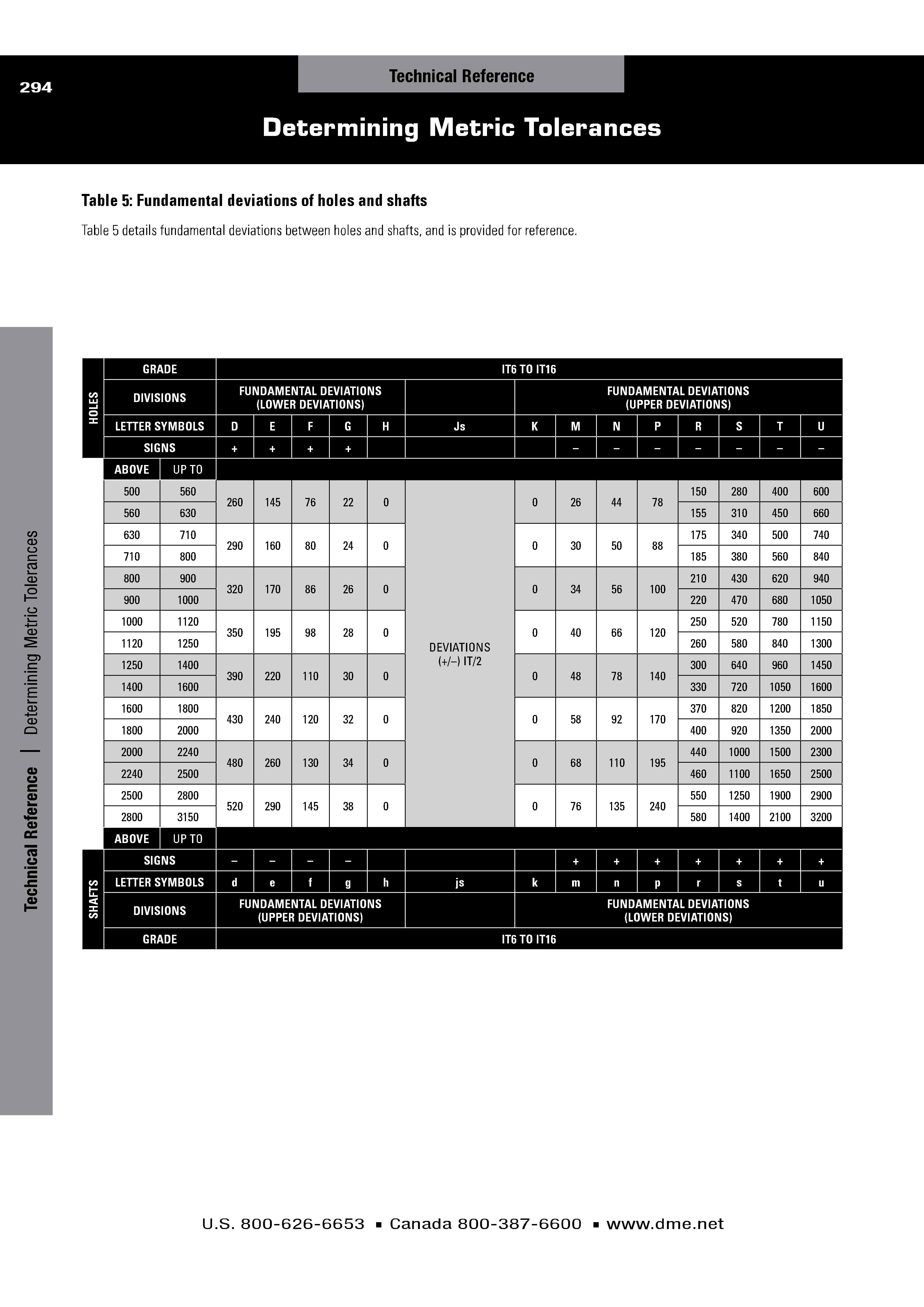
Table 6: Tolerances for inside dimensions (holes)
Table 6 details tolerances for inside dimensions (holes) based relative to the tolerance symbol. Upper and lower values are provided as either
positive or negative (or zero) values relative to the nominal size chosen. Pick the range in which the desired nominal value falls into, and
then either add or subtract the tolerances to end the upper and lower tolerance range for the desired nominal size.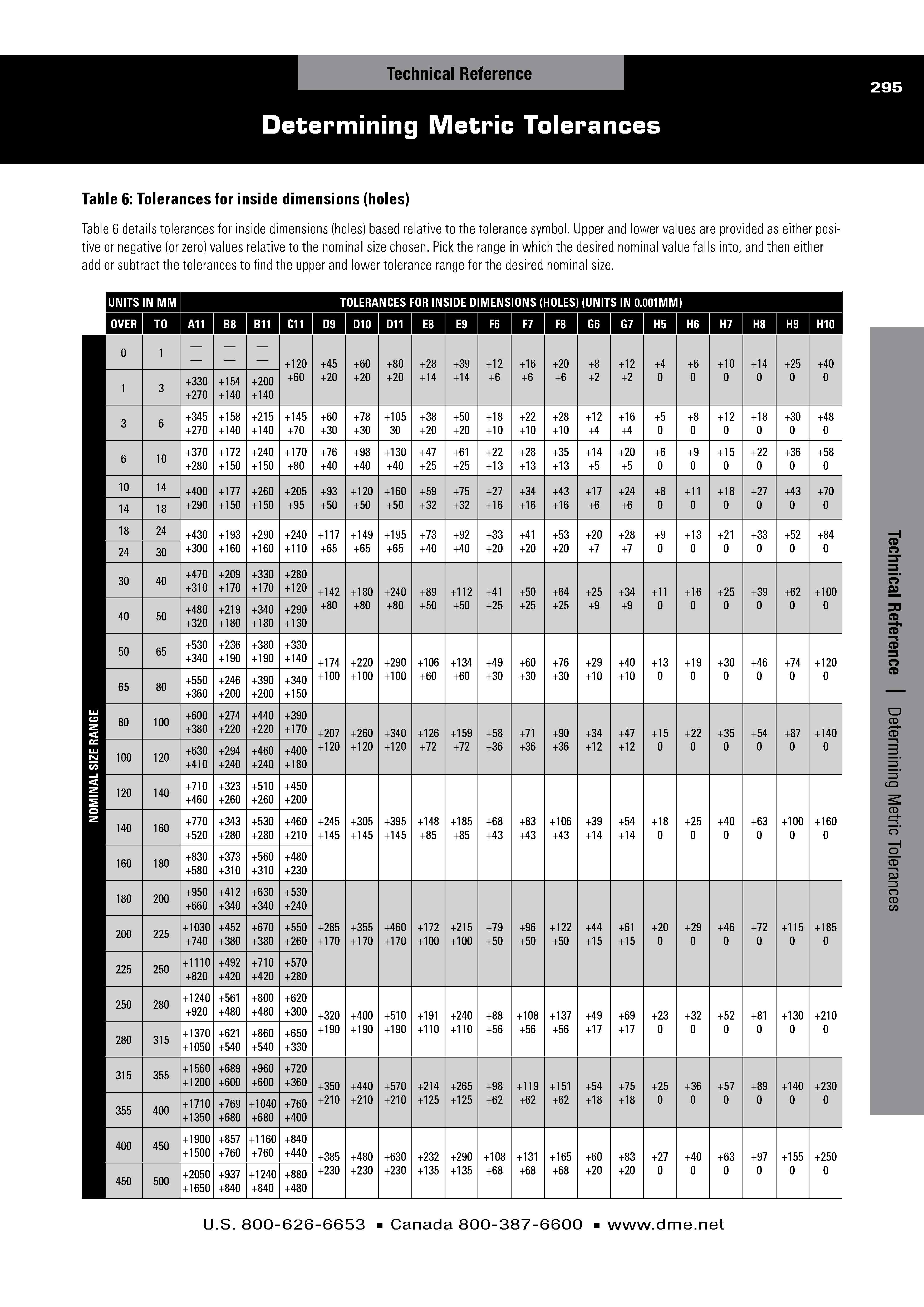
Table 6: Tolerances for inside dimensions (holes) continue
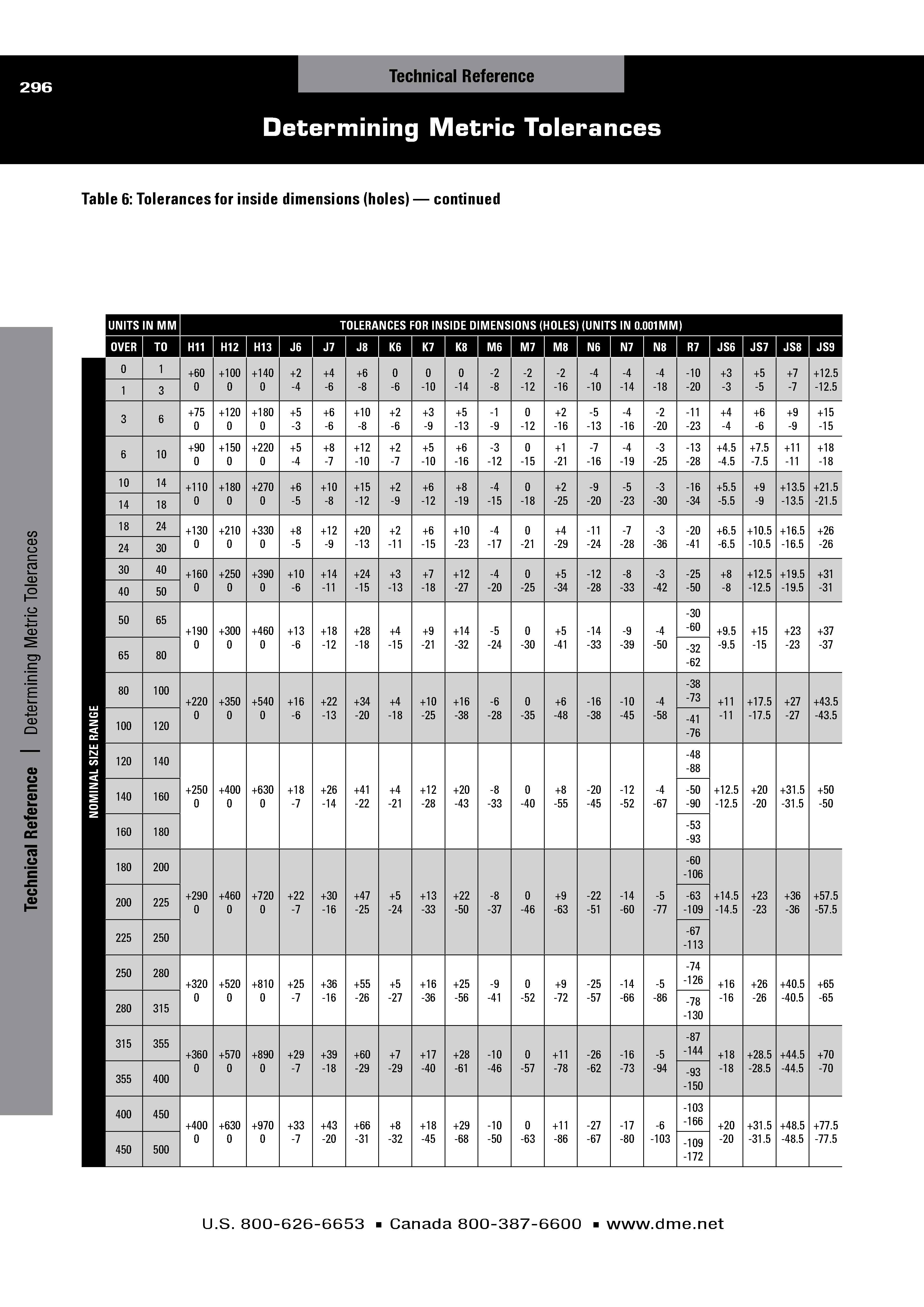
Table 6: Tolerances for inside dimensions (holes) continue
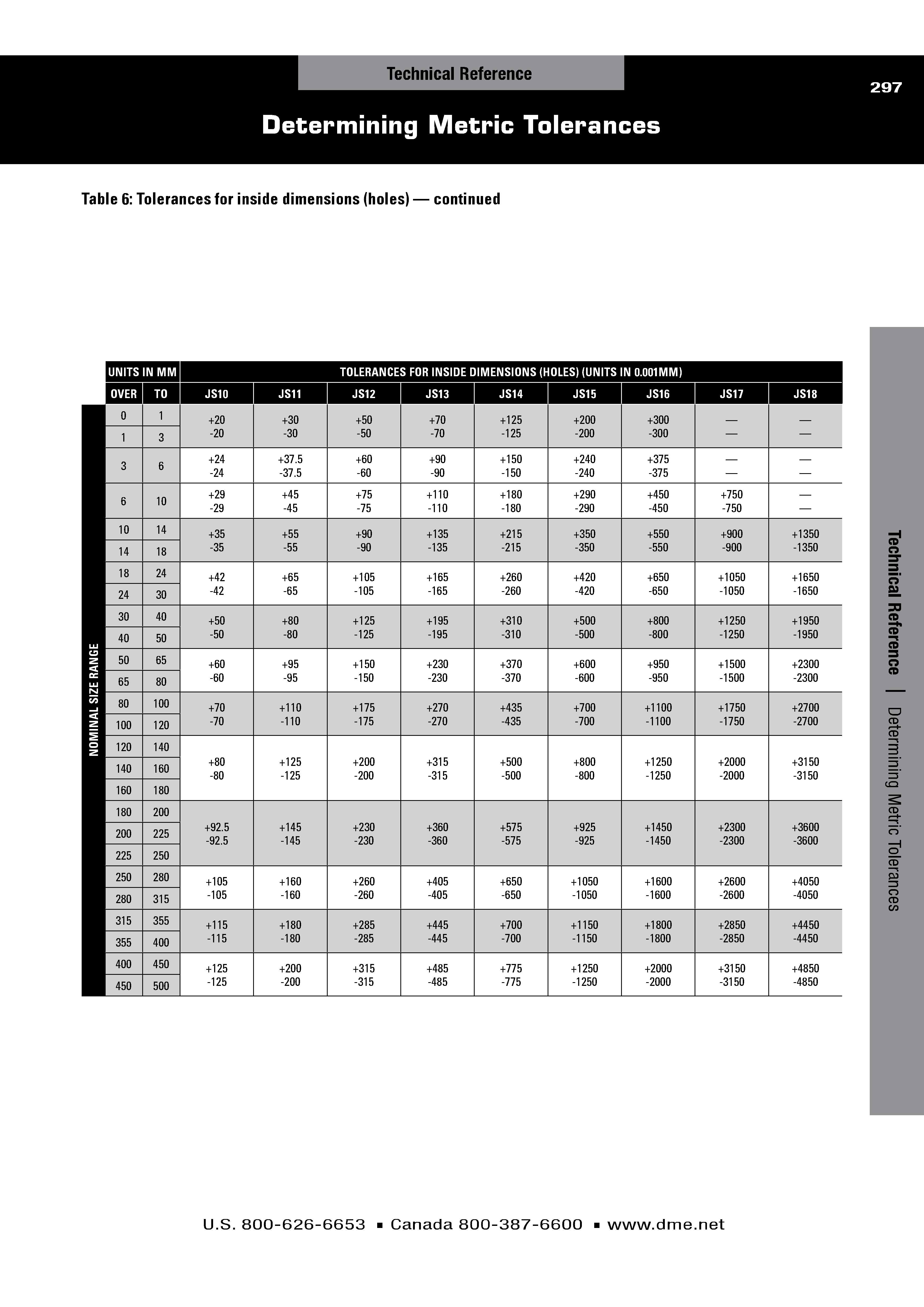
Table 7: Tolerances for outside dimensions (shafts)
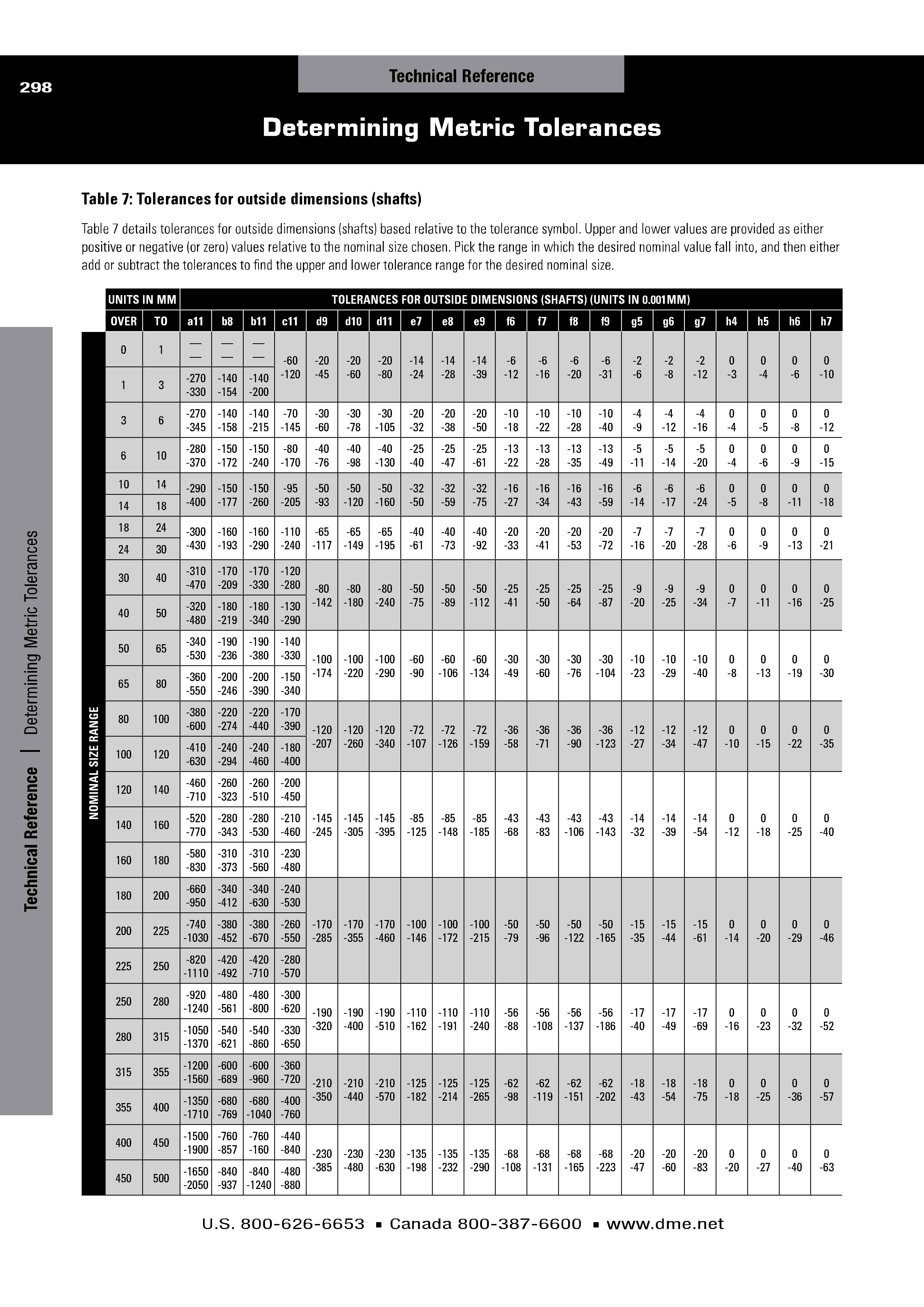
Table 7: Tolerances for outside dimensions (shafts) continue
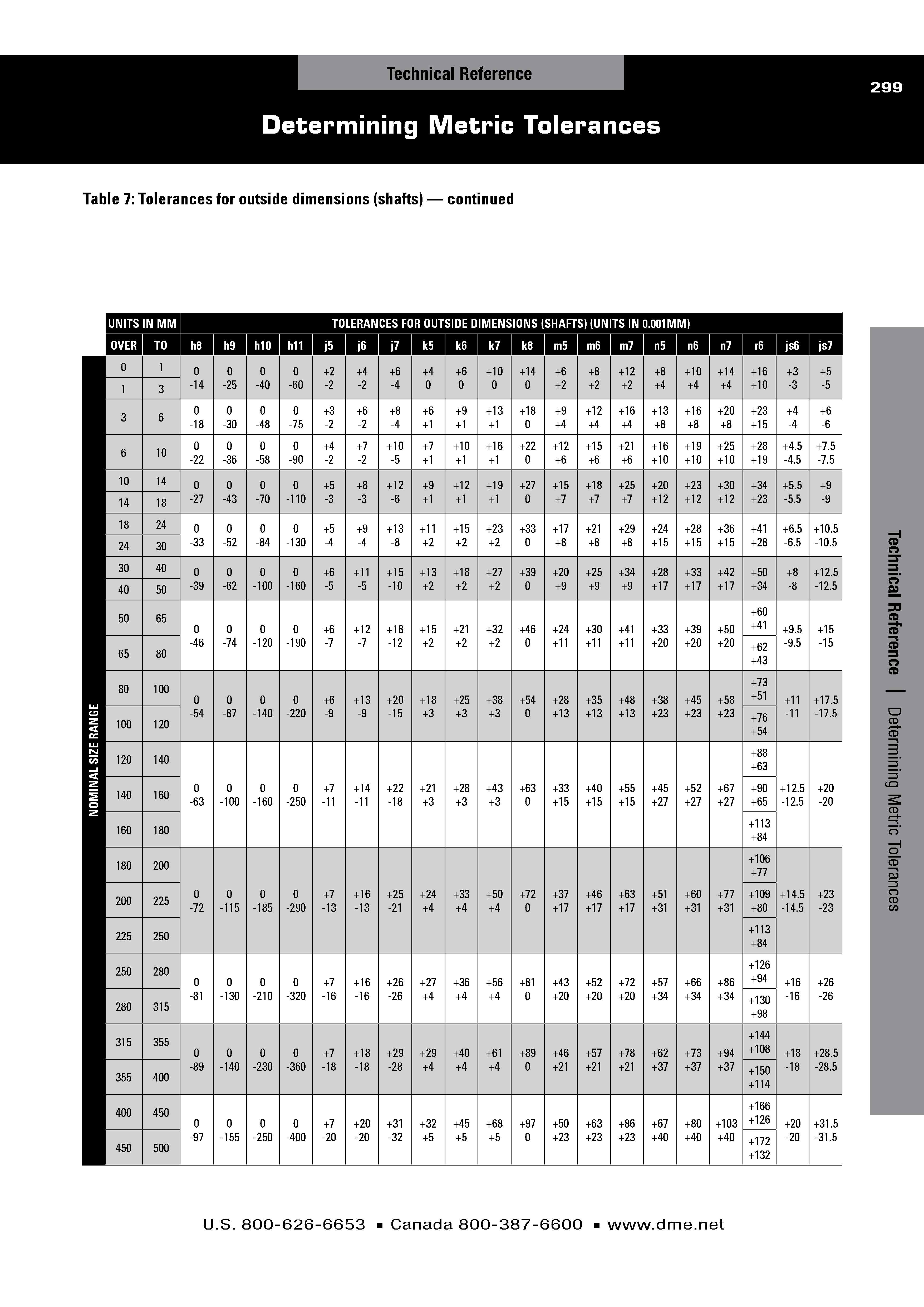
Table 7: Tolerances for outside dimensions (shafts) continue
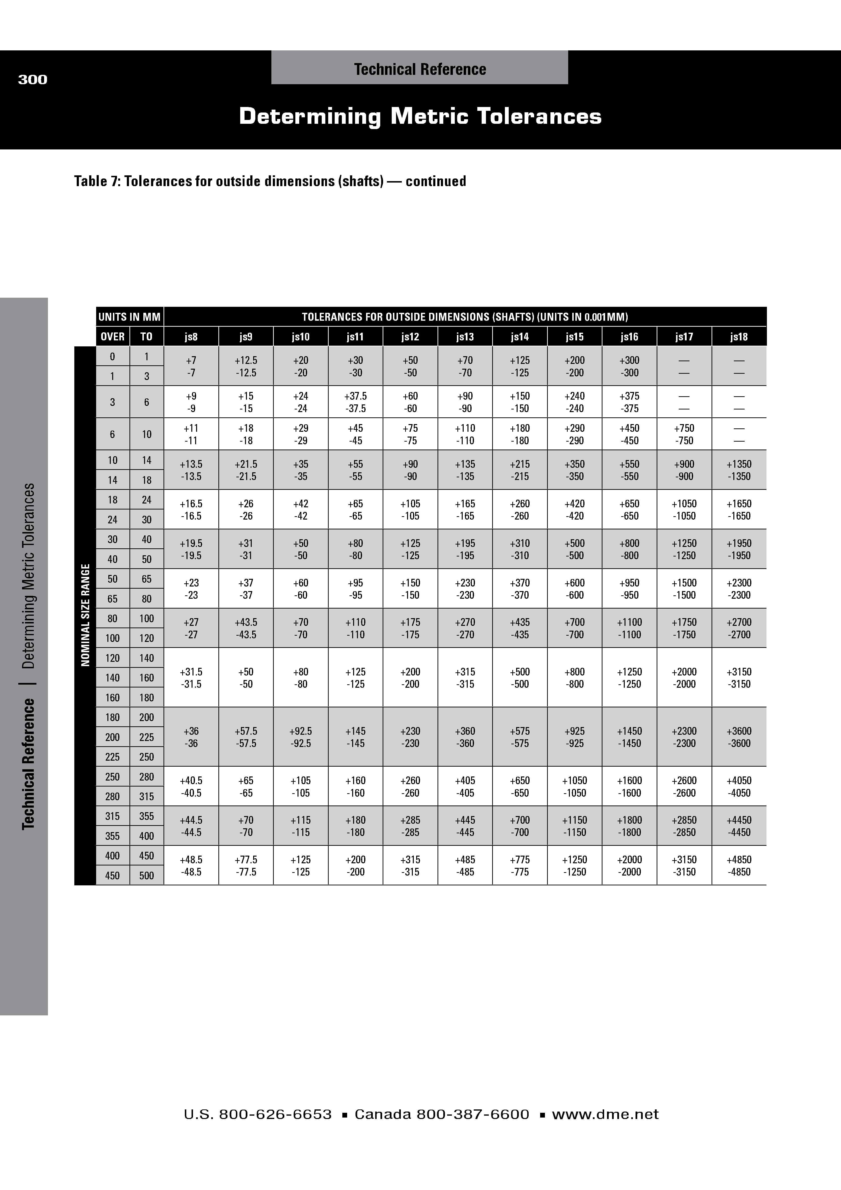
Table 8 details tolerances for inside dimensions (holes)
based relative to the tolerance symbol. This table works the same way as Table 6, but is
pulled from a different source (ANSI standards) and details S7 and U7 ?ts. Pick the nominal size value that is closest to the desired nominal size to
determine the required tolerance range relative to the chosen tolerance symbol.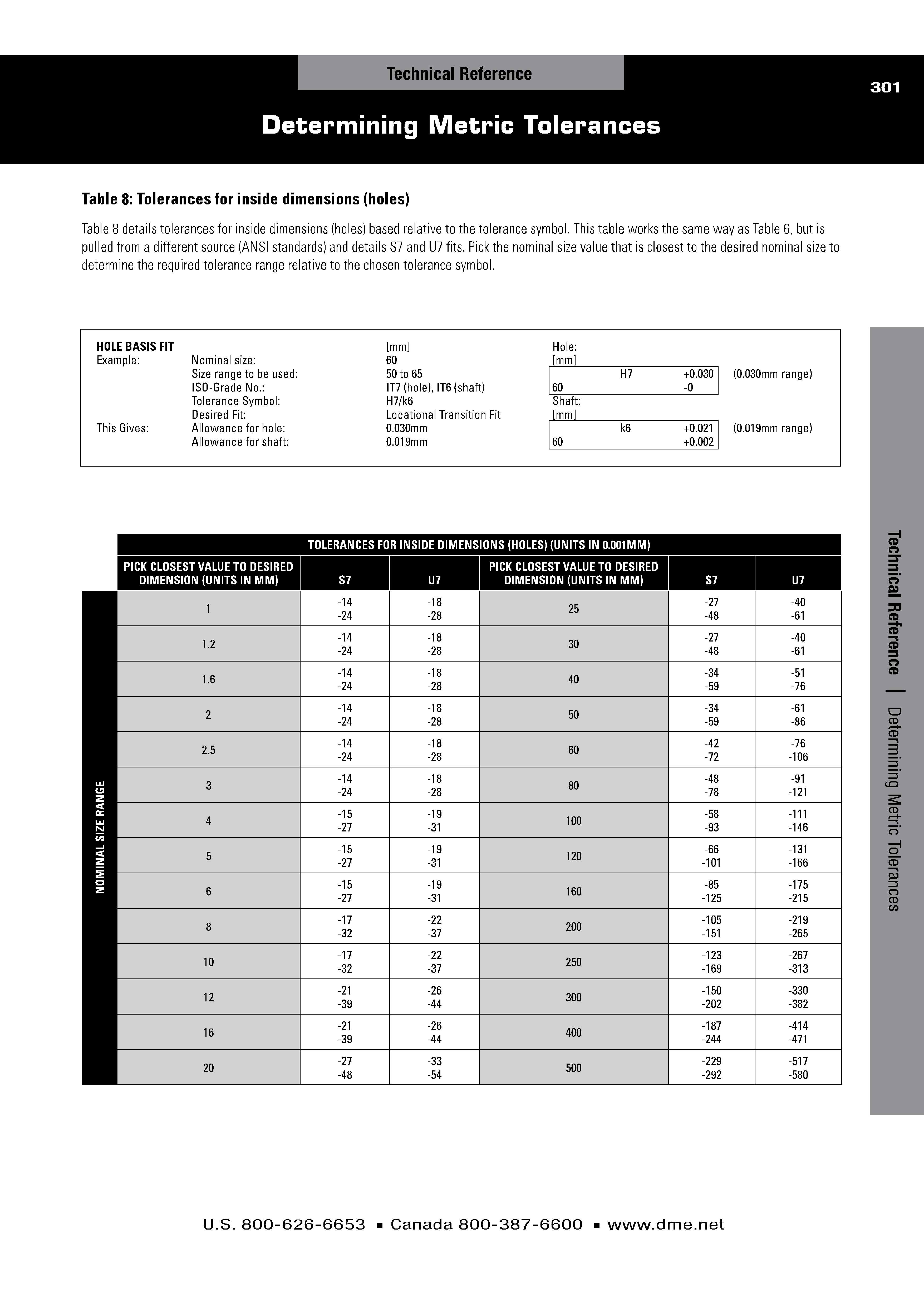
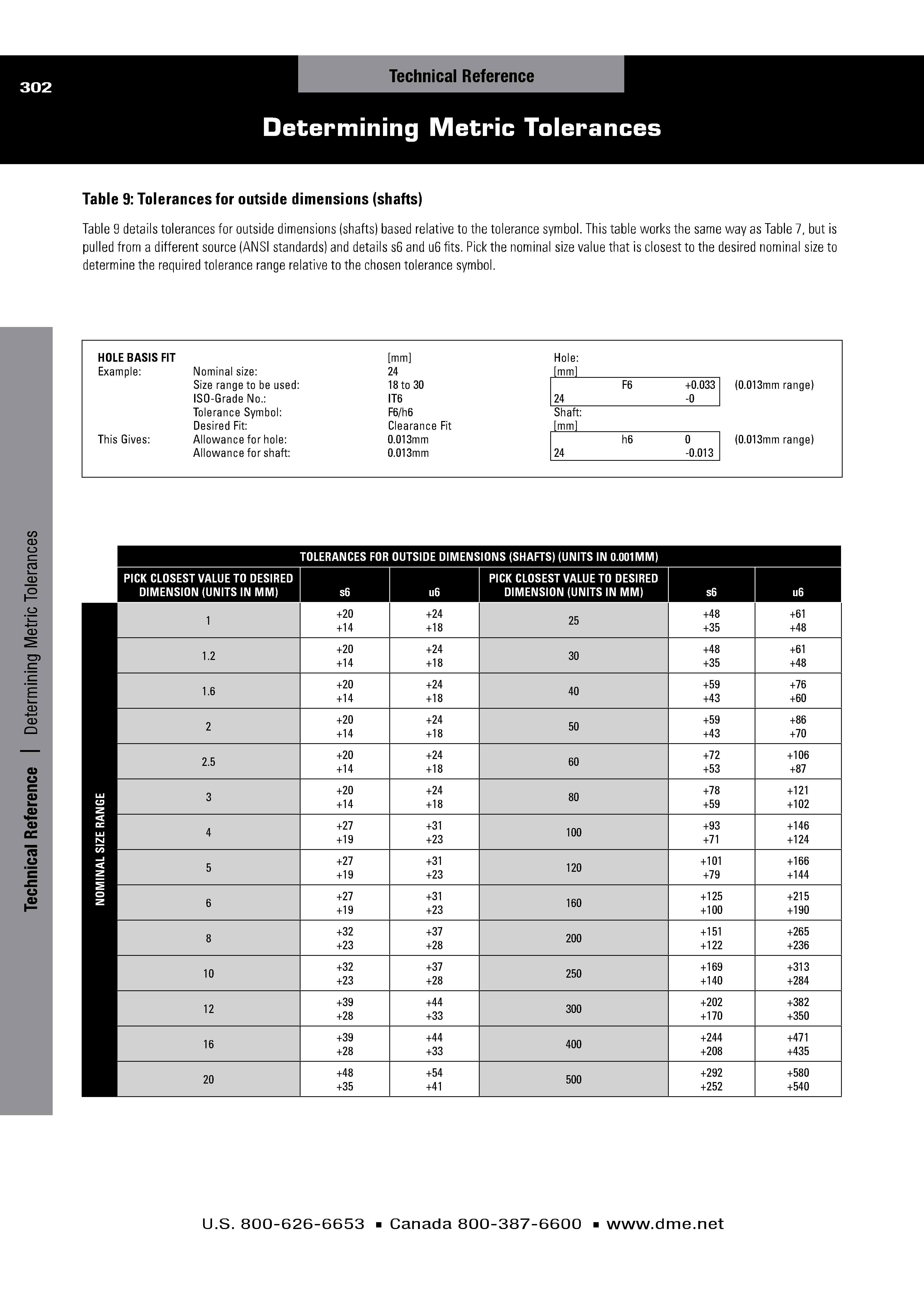
Table 9: Tolerances for outside dimensions (shafts)
Table 9 details tolerances for outside dimensions (shafts) based relative to the tolerance symbol. This table works the same way as Table 7, but is
pulled from a different source (ANSI standards) and details s6 and u6 ?ts. Pick the nominal size value that is closest to the desired nominal size to
determine the required tolerance range relative to the chosen tolerance symbol.