Our company supplies professional plastic injection mold tool design services for customers in full 3D formats from your 2D or 3D CAD files. Our company's design team have 10 employees, and have 6 senior injection mold tooling engineers. Our
engineers can design injection molds from basic single cavity prototype to complex, multi-cavity long life production molds.
Our designer also can create a comlex part 3D from your actual sample. Please contact us:
sales@viewmold.comor submit a quote online..
We support multiple file formats. Our powerful Unigraghics CAD system transforms your part data into a precision 3-D solid modeled tool design.
We can also create a complete 3D model of your intended part or convert your 2-D drawings to a 3-D solid CAD model.
We can review your CAD files or part drawings, help ensure your product can be manufactured and provide feedback on possible quality issues or areas in need of improvement.
If we find an area in your part that can not physically be manufactured or has quality issues, we will make a modification to your 3-D CAD model with a
solution that best fits the application and return it to you for approval. We utilize Moldflow to analysis the products and simulate injection molding processes to
avoid potential process defects (such as: sink, warpage), enable you to predict and solve process problems in the earliest stage. We believe that a quality tooling comes from a quality tooling design.
The following information is some par guidelines that can be summed up in just a few design rules.
1 Injection molding design better uses uniform wall thicknesses throughout the part. This will minimize sinking, warping, Sink Marks is the plastic solidifies in the mold it freezes from the outside
(near the mold surface) toward the inside. In thick sections this results in
inward pulling stresses (due to contraction) that can cause sink marks in the
outer surfaces of the part. Thicker and non-uniform wall thicknesses can often result in sinks in the
material due to the same solidification physics described above.
2 Warpage is trouble issue, serious warpage will cause the disintergration of project.
Our engineer team have researched warpage for 10 years, and found some warpage is caused by unreliable injection mold design,
some warpage is caused by unreasonable injection molding condition.Suitable gate position and enough ejection will improve warpage.
In 2018, Our engineers found that the most warpage can be improved by adjusting injection molding condition. Injection molding pressure, time, hold molding pressure, time, step, mold temperature and ejection are keys.
Sometimes the extra cooling time can improve warpage, but it will cause extra production cost. We try our best to avoid the solution.
residual stresses, and improve mold fill and cycle times.
3 Injection molding design better uses generous radius at all corners. The inside corner radius should be a minimum of one material thickness.
4 Injection molding design better uses the least thickness compliant with the
process, material, or product design requirements. Using the least wall
thickness for the process ensures rapid cooling, short cycle times, and minimum
shot weight. All these result in the least possible part cost.
5 Design parts of the injection molding to facilitate easy withdrawal from the mold by providing draft (taper) in the direction of mold opening or closing.
6 Injection molding part design better uses ribs or gussets to improve part
stiffness in bending. This avoids the use of thick section to achieve the same,
thereby saving on part weight, material costs, and cycle time costs.
Rib-to-wall thickness ratios: Thin ribs on thicker walls may provide stiffness but also can result in
sinking on the outside of the wall. This rule-of-thumb guideline should help
keep this from happening Watch rib-to-wall thickness ratios prevent sink, the thickness of the rib
should be about 0.7 of the thickness of the wall.
Here are some general injection molding part design guidelines to help you for
learning the injection molding design, but for perfect products, you have
to learn more and practice more in your work. You also contact us, our injection mold tooling design engineers will
provide you more professional injection mold tooling design suggestions.
a)Viewmold injection mold standards Description
b)Mold Series Description
Viewmold "A"Series, Viewmold "B"series, Viewmold "X"Series
Viewmold "AX"Series, Viewmold "T"series, Viewmold "RG"series
c) Common mold steels and applications for injection mold standard
Defines the common steel types and their applications
d) Drawing format and standards
Defines the Viewmold 2-D drawing layout and standard drafting aids for the Block-out, Preliminary, and final design drawings.
e) Solid Model Geometry format, construction, and standards
Defines the Unigraphics Solid Modeling requirements, Viewmold data layering specifications, Viewmold construction techniques, general mold functionality fit and function standards, and Viewmold design for manufacturability requirements.
A) Mechanical Slide Design Standards
B) Hydraulic Slide Design Standards
C) Lifter Design Standards
Section 3: Runner System Standards and Design
Contents:
A) Surface Runner and gate Design Standards
B) Hot Runner Design Guidelines
C) Three plate runner and Pin-Point Gate Design Standards
A) Ejector pin design standards
B) Guided ejection design standards
C) Spring return standards
D) Hydraulic ejector standards
E) Press Knock-out (PKO) design standards
a) Hydraulic Standards
b) Pneumatic Standards
Contents:
a) Viewmold injection Mold Standard Description
b) Moldbase Series Description
c) Common mold steels and applications for Viewmold molds
d) Drawing format and standards
e) Solid Model Geometry format, construction, and standards
*Built for medium production. Viewmold molds are not recommended for abrasive or corrosive materials without written customer approval, and appropriate plating of all part related items.
*All mold plates must be a minimum of SAE 1030 steel. AISI 4130 steel is commonly used due to price and availability of SAE 1030 steel.
*Core and Cavity blocks (In-solid designs), Core and cavity inserts, sub-inserts, and other non-moveable items are to be constructed with a minimum of P-20 steel.
*Slides, lifters, bar ejectors, and similar actions can be constructed of P-20 steel also, but must have a minimum of 3-degrees shut-off on all seal surfaces. Nitriding is required otherwise, as in the case of straight wall lifter designs. Hardened S-7 steel should be considered for all lifter designs.
*Slides must have lamina bronze wear plates with grease grooves.
*Ejector plates must be guided with two guide pins and ejector guide bushings minimum. The amount will be determined based on the mold size and number of ejector plate activated actions.
*Integral parting line locks must have lamina bronze wear plates if the interlock angle is less than 10-degrees. Standard inserted hardened interlocks are acceptable as the part design permits. All interlock designs must protect internal shut-offs.
*Cooling is required in all part-related features insofar as possible, and in mold plates as required for specific temperature control, such as in plates encompassing hot runners, valve gate actuators, etc.
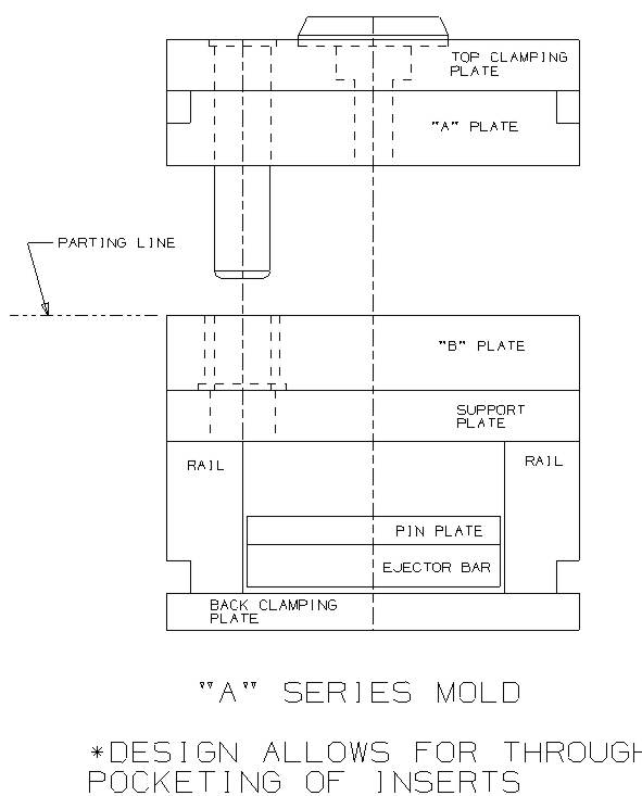
 "A"Series Mold: Design allows for through pocketing of inserts (refer to drawing S1-1)
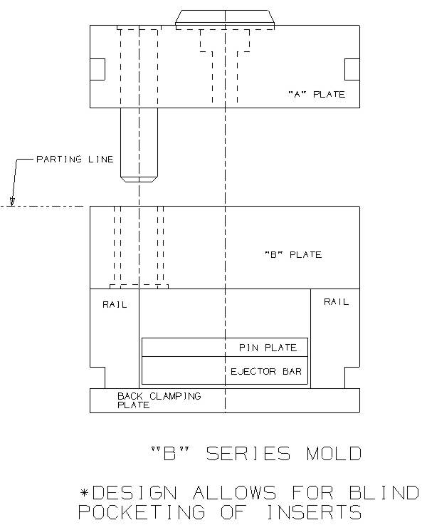
"B"Series Mold: Design allows for blind pocketing of inserts and solid,core/cavity (refer to drawing S1-2)
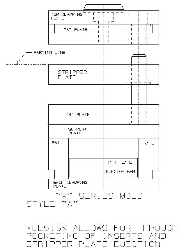
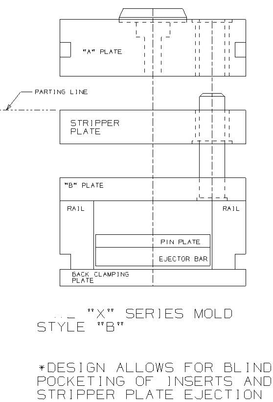
"X"Series Mold: Design allows for through pocketing of inserts and stripper plate ejection (refer to drawing S1-3). design allows for blind pocketing of inserts and stripper plate ejection (refer to drawing S1-4)
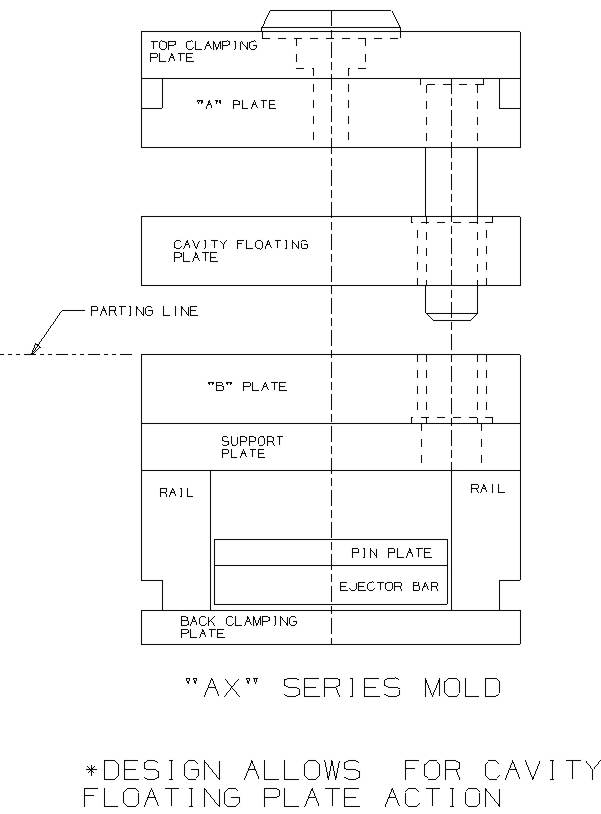
"AX"Series Mold: Design allows for cavity floating plate action (refer to drawing S1-5)
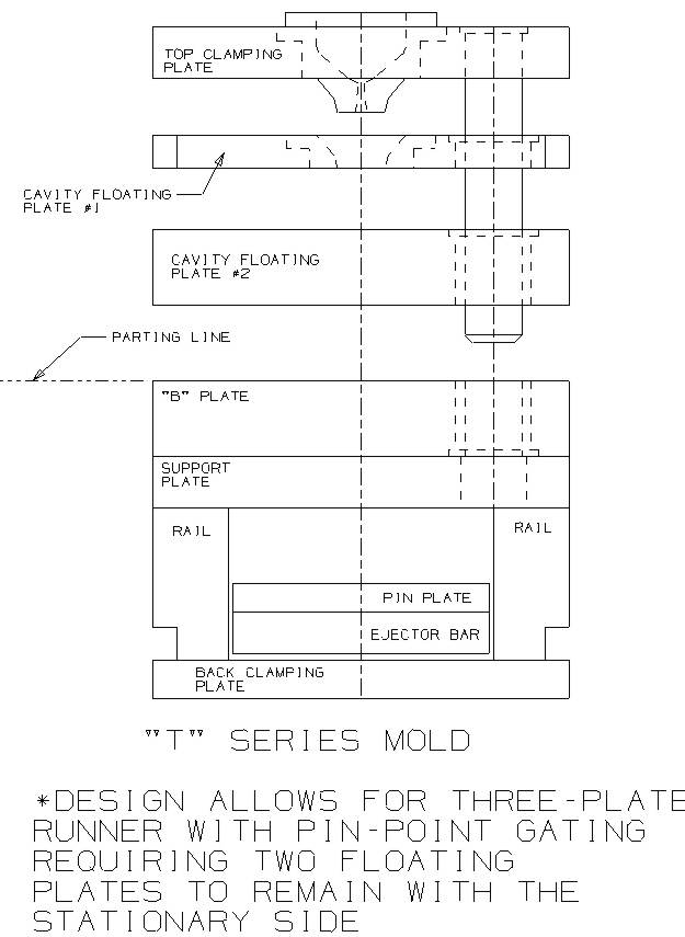
"T"Series Mold: Design allows for three-plate runner with pin point gating requiring two floating plates to remain with the stationary side (refer to drawing S1-6)
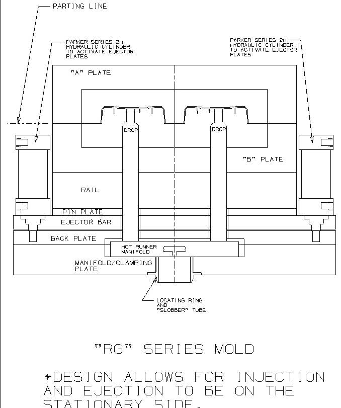
"RG"Series Mold: Design allows for injection and ejection to be on the stationary side (refer to drawing S1-7) c) Common mold steels and applications for Viewmold molds
Defines the common steel types and their applications. Examples given are the most common types as used by Viewmold. The Customer will specify the general steel types. HRS – Hot rolled steel –SAE 1030: Ejector housing plates, clamping plates, back-up plates, support pillars, mold “feet” (NOTE: Due to the limited availability of HRS, all mold plates can be 4130/4140 (#2) steel.)
4130/4140 (#2 Steel) - Prehardened 30-36 RcC : General mold base plates
P-20 – Prehardened 30-36 RcC : High grade base plates, large cores and cavities, core and cavity inserts, slides, sub-inserts
420M (Prehardened 420 stainless steel) - Prehardened 30-35 HRC : large cores, cavities, inserts, slides
S-7 - Air hardening 54-56 RcC – Cavities, Cores, inserts, lifters, stripper rings, slides
420 SS - Stainless 50-52 RcC – Cavities, cores, slides, inserts
FP-100 Lamina Bronze – Wear plates – Must provide grease grooves. O-1 - Oil hardening 58-62 RcC – Gibs, slide guides, wear plates Ampco-18 – Gibs, slide guides, and wear plates
Over-all dimensions (length, width, mold stack height, stroke, plate thickness. Etc.).
mold designated
Views to clarify actions, water layout, and special features
views as required (Example: 3-Plate molds, Floating cores, etc.)
Enlarged view of gate(s) with dimensions
Steel types and hardness
Watts, Volts, Amps per zone, Hot Runner information
Power and Thermocouple connectors/junction box
General Notes and tolerances, Texturing information, special sequencing notes, paint requirements, coating/plating requirements, etc.
Material List to include quantity required, detail number, over-all dimensions, catalog number, material type, and supplier (Standard Viewmold format)
Water and hydraulic connector information noted.
Water and hydraulic thread sizes noted.
Eyebolt sizes noted.
Completed title block with material and shrink, press size and model, etc.
Press tie bars shown in plan views
Layer list if applicable
Detail views and dimensions as required. NOTE: The 3-D solid model will be considered dimensioned details? unless the Customer requires dimensioned detailed views. We will maintain the ?data-driven?approach unless otherwise specified by the customer and compensated appropriately.
 Tooling Data Sheets
e) Solid Model Geometry format, construction, and standards
Defines the Unigraphics Solid Modeling requirements, Viewmold data layering specifications, Viewmold construction techniques, general mold functionality fit and function standards, and Viewmold design for manufacturability requirements.
Final 3-D Mold Data to Include:
All components, actions, and blocks in Solid Model format. NOTE: The Viewmold layer list must be followed. The data must represent the actual steel conditions insofar as possible
all vents, vent clearances, and parting line clearances
any sub-inserts required for in-process ECNs and/or corrections (NOTE: Design data must reflect steel conditions insofar as possible)
Engraving information (2-D Geometry with depth and width noted is acceptable)
All Hot Runner/Nozzle components, including electrical connector pockets/junction boxes, etc.
All hydraulic cylinders. NOTE: Complex hydraulic plumbing should be modeled as needed
All lifting holes, brackets, lifting straps, safety straps, protecting pillars
Water manifolds if required
Press platen and tie bars