Overview
This describes object types, database routines, coordinates systems,
and a description of some of the object types that are important to Open C
API programmers. The following topics are covered:
NX Object Types
NX uses object types to identify its objects. All of the objects
and their subtypes are predefined as symbolic constants in the header file uf_object_types.h for use in C programs.
Update and Delete
After you create an object and then edit the object, the object is placed
on the update list. If you then delete this object without peforming an
update using UF_MODL_update an informative message may be placed in the
syslog stating that the object has been placed on the update list.
The best procedure is to update the part before deleting the object.
For example, create the point, edit the point, invoke update to perform
the update on the point, then delete the point. In this manner, the point
would not appear on the update list when delete is invoked. Additionally,
you could improve the process by invoking update after you have completed
all edits rather than invoking update after each edit.
Database Routines
Open C API has a set of subroutines based on NX routines which
allow you to access the database. Because of the complex nature of the
NX database, only a limited capability to modify data is provided.
The capabilities provided include simple object creation and modification,
object attribute creation and modification, object independent data access
and modification, database cycling, notes/labels creation, group creation
and access
Coordinate Systems
The Absolute Coordinate System (ABS CSYS) is the coordinate system from
which all objects are ultimately referenced. As an example, all data for
points use this coordinate system. The Work Coordinate System (WCS) is
used in determining orientations and angles. This combination of using
both coordinate systems is called the CONSTRUCTION SPACE in Open C API.
As an example when creating an arc, the center, orientations and angles
are determined from the WCS.
Matrices
A (3x3) orthogonal matrix for mapping absolute space and its associated
coordinate system. The following text and illustration explain the algebraic
representation of matrix as it is used in NX and in Open C API.
See the uf_csys.h and uf_mtx.h chapters.
CALCULATED For a 3x3 orthogonal matrix R
   i    j    k
X  R[0] R[1] R[2]
Y  R[3] R[4] R[5]
Z  R[6] R[7] R[8]
where vectors i, j, k are normalized direction cosines
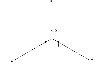
Figure 1 Normalized i, j, k vectors
Arcs
An arc is any part of a circle. In NX, zero degrees is along
the positive X-axis from the arc center, and the angles are incremented
counterclockwise. The illustration in Figure 2 explains the geometric representation
of an arc as it is used in Open C API. See the uf_curve.h chapter.
Arcs are created with respect to the Construction Space CSYS. The construction
space CSYS is parallel to the WCS and located at the ABS CSYS origin. The
arcs were created with:
Center = (2.0, 3.0, 1.0) and Radius = 0.5.
Arc 1 was created with the WCS equal to the ABS CSYS.
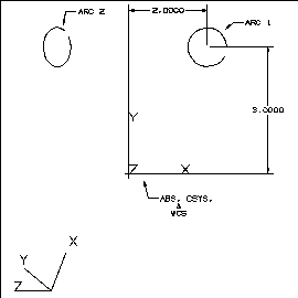
Figure 2 Arc1 with respect to CSYS
Arc 2 was created with the WCS moved and rotated. An Open C API function
created the arc in the Construction CSYS, which is the same as if the WCS
was rotated, but NOT moved.
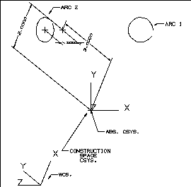
Figure 3 Arc2 created with transformed WCS
Splines
A spline is a smoothed curve defined by input points and possibly by
additional vector constraints. The spline curve and its derivatives are
defined in the following illustration for a cubic spline segment.

Figure 4 Spline
There are many different types of spline curves. The ones used in NX
are Non-Uniform Rational B-spline curves, sometimes referred to as "NURB"
curves.
A Bezier curve is a B-spline curve that consists of only a single segment.
A B-Spline curve is a multi-segment curve represented by a list of points
called poles.
You can consider a spline curve as a list of Bezier curves, and a Bezier
curve as a special type of B-spline curve.
See the functions in the uf_modl.h chapter.
Degree of a Spline
A Spline has a degree. Degree is a mathematical concept; it actually
refers to the degree of the polynomial or rational functions used to describe
the curve.
A higher degree curve is stiffer in the sense that you have to move
its poles a long way to produce any appreciable change in the shape of
the curve. Lower degree curves are more pliable, and tend to follow their
poles much more closely.
In NX, the degree of a Spline must be between 1 and 24. However,
we recommend the use of cubics (a degree of 3) when creating Splines. Creating
lower degree curves results in faster performance during subsequent operations
such as machining, display, etc. Using higher degree curves reduces the
chance of transferring data to other systems which may not support them.
Also, the creation of a high degree curve through many points may lead
to unpredictable results.
Bezier Curve Degree
To create a Bezier, single segment curve, set the degree to one less
than the number of points input.
B-Spline Curve Degree
For a B-spline curve, the degree is independent of the number of points.
You select the desired degree knowing that the minimum number of points
is one more than that degree.
Minimum/Maximum Number of Points
For a Bezier curve, the minimum number of points is two (minimum degree
of 1) and the maximum number of points is 25 (maximum degree of 24 + 1).
For a B-spline curve at least degree + 1 points must be specified.
Creation Options
The system interprets the specified points in one of two ways: as points
through which the curve must pass; or as points defining the location of
the poles.
Points on Curve
Allows you to define a list of points through which the curve will pass.
The curve interpolates each specified point, as shown on Figure 1-5. When
you use this option, you have control over the curve in the sense that
it will always pass through the points that you specify. However, take
note that specifying a high degree curve using this option may produce
unpredictable results.
Poles
Allows the system to interpret the specified points as poles of a control
polygon. In general, these poles do not lie on the resulting curve, as
shown in Figure 1-5 . Using the Poles option gives you much better control
of the overall shape and character of the curve since the resulting curve
follows the shape of the control polygon. Using Poles gives you a much
better chance of avoiding unwanted undulations (reversals of curvature)
in the curve.
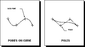
Figure 5 Bezier: Points On Curve & Poles
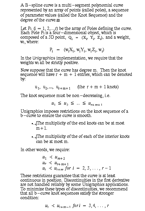
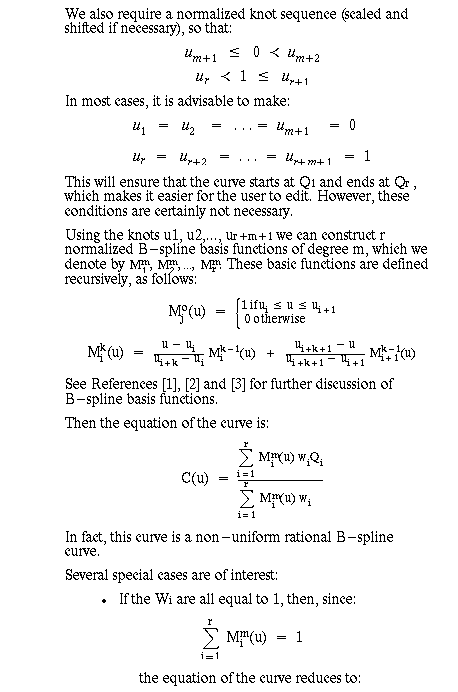
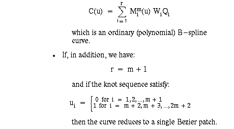
Mathematical Composition of a Spline
References
[1] Rogers and Adams Mathematical Elements For Computer Graphics,
McGraw Hill, 1976
[2] Gerald Farin Curves and Surfaces For Computer-Aided Geometric
Design, Academic Press, 1988
[3] de Boor A Practical Guide To Splines Springer-Verlag, 1978
Conics
A conic can be one of three types, dependent on parameter values: an
ellipse, parabola, or hyperbola. The following illustration explains the
geometric representation of a conic as it is used in NX and in
Open C API.

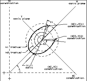
Figure 6 Conic
Refer to the routines in the uf_curve.h chapter.
Cylinder
A cylinder is generated by a line, not in the plane of a closed curve
but passing through every point of the curve, and maintaining one special
direction. The following illustration explains the geometric representation
of a cylinder as it is used in NX and Open C API.
NOTE: Open C API routines use U/V parameter values that are not normalized
between the range of zero and one. Appropriate mathematical manipulation
of these parameters allows access to any point on the face.
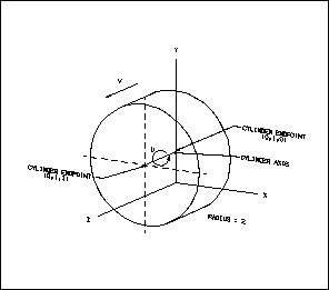
Figure 7 Cylinder
Refer to the routines in the uf_modl.h chapter.
Cones
A cone is generated by moving a straight line so that the line always
touches a circle, and passes through a fixed point. The following illustration
explains the geometric representation of a cone as it is used in NX
and Open C API.
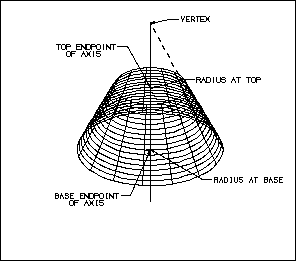
Figure 8 Cone
See the uf_modl.h chapter.
Bodies of Revolution
A body of revolution is generated by revolving a given curve about an
axis. The following illustration explains the geometric representation
of a body of revolution as it is used in NX and Open C API.
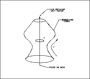
Figure 9 Body of Revolution
See the uf_modl.h chapter.
Ruled Sheets
A ruled sheet is generated by assigning a one-to-one correspondence
between points on two specified curves, and then connecting corresponding
points by straight lines. The following text and illustration explain the
geometric representation of a ruled sheet as it is used in NX
and Open C API.
NOTE: This function creates a sheet defined by a B-surface.
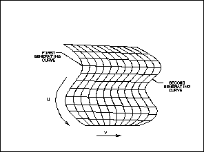
Figure 10 Ruled Sheet
See the uf_modl.h chapter.
Bounded Planes
A plane generated by selecting a string of end-to-end curves (lines,
arcs, splines, conics) for the boundary. The curves selected must be co-planar,
chainable, and form a closed shape. U and V grids can be displayed on a
Bounded Plane. The following text and illustration explain the geometric
representation of a bounded plane as it is used in NX and Open C
API.
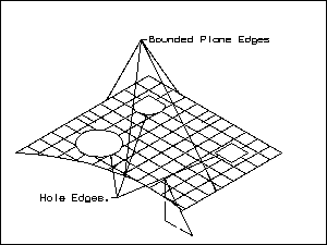
Figure 11 Bounded Plane
See the uf_modl.h chapter.
Sheets Created Through
Curve Mesh
These are free-form curved sheets that interpolate or pass through an
intersecting network of curves. The following illustrations explain the
geometric representation of a curve mesh sheet as it is used in NX
and Open C API.
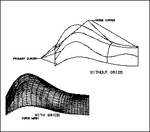
Figure 12 Curve Mesh Sheet
See the uf_modl.h chapter.
B-surface Sheets
These are sheets described by a B-surface. You may create a B-surface
using a variety of techniques.
See the uf_modl.h chapter.
Difference Between a Bezier Surface and a B-spline
Surface
Both the Bezier surface and the B-spline surface are referred to as
a B-surface because; a Bezier surface is a special type of B-spline surface,
and a B-spline surface is a rectangular array of Bezier surfaces. The Bezier
surface is a B-spline surface which has a single patch, while the B-spline
surface is a multi-patch surface. A B-surface is composed of the following:
- A rectangular array of points which lie near the surface, but not on
it (Poles)
- Two sequences of parameter values, one for each direction (Knot Sequences)
- Degree Values for each direction of the surface
Although there are many different types of B-spline surfaces, the type
used by NX is the "Non-Uniform Rational B-spline" surface,
sometimes referred to as NURB surfaces
Degree of a Surface
The degree of a B-surface is determined by a mathematical concept which
incorporates the degree of the polynomial or rational function used to
describe the surface. A B-surface has a degree in both the U direction
and in the V direction.
In NX, the degree of a B-surface (in either direction) must
be between 1 and 24. However, we recommend that you use cubics (a degree
of 3) when creating B-surfaces. Creating lower degree surfaces results
in faster performance during subsequent operations such as machining and
display. Using higher degree surfaces reduces the chance of transferring
data to other systems which may not support the higher resolution. Additionally,
the creation of a high degree surface through many points may lead to unpredictable
results.
A higher degree surface is stiffer in the sense that you must move its
control vertices a longer distance to produce any appreciable change in
the shape of the surface. Lower degree surfaces are more pliable, and tend
to follow their control vertices much more closely.
Control vertices roughly correlate to the degrees of freedom of the
surface. To increase the degrees of freedom for a surface, you can:
- Increase the number of points per patch (i.e., the degree)
- Increase the number of patches for the surface
Avoid Overly Complicated B-surfaces
When building B-surfaces you should attempt to minimize the number of
patches used to define the surface. Limiting the number of patches will
improve the performance of downstream applications, and produce smoother
surfaces.
Some creation techniques do approximation of the input geometry when
building the B-surface, so they ask you to enter tolerances to control
this approximation process. When using a creation technique which requires
a tolerance, make certain the tolerance specified is reasonable. Very small
tolerances will produce surfaces with large amounts of defining data and
may impair the smoothness of the surface. All techniques using approximation
ask for a deviation tolerance, i.e., the maximum distance between the input
geometry and the resulting surface. Some techniques which will be approximating
curves will also ask for an angle tolerance to define the maximum error
between the tangent vectors of the input curves and the approximations.
Curve approximation can be adversely affected by the angle tolerance. Even
when the distance tolerance has been achieved, it is possible that more
segments would have to be added to achieve angle tolerance. If you find
that the surface created has an excessive amount of data or that surface
creation is taking too long, you may want to increase the angle tolerance
or possibly make the angle tolerance very large to, in effect, remove that
tolerance from consideration.
In reality, there is a maximum amount of data for the definition of
a B-surface. However, this maximum size is so large that it should rarely,
if ever, be exceeded. If however, you do exceed the maximum size, an error
message will be displayed and no surface created. The cause of this error
would probably be approximation tolerances which are too small. Increasing
these tolerances, especially the angle tolerance, should correct the problem.
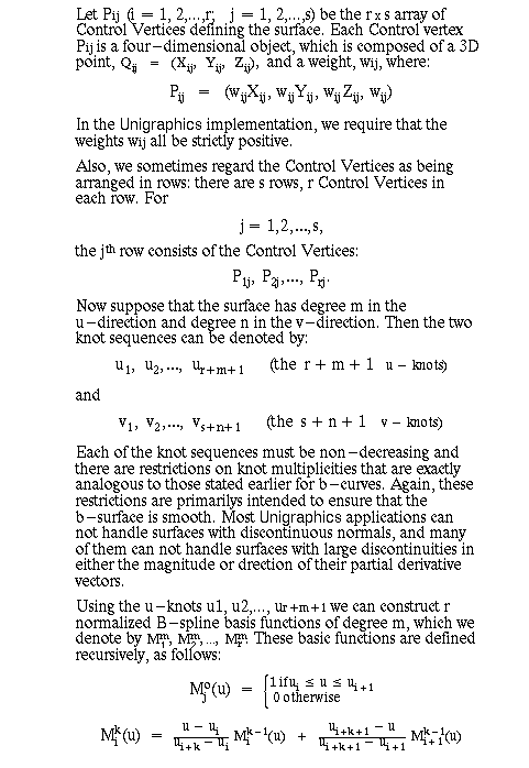
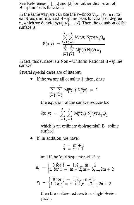
Mathematical Composition of a B-surface
References
[1] Rogers and Adams Mathematical Elements For Computer Graphics,
McGraw Hill, 1976
[2] Gerald Farin Curves and Surfaces For Computer-Aided Geometric
Design, Academic Press, 1988
[3] de Boor A Practical Guide To Splines Springer-Verlag, 1978


