To define a bisector line:
-
Select two nonparallel lines. The selected lines do not have to intersect.
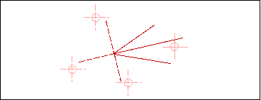
The four possible bisector lines rubberband as you move the cursor around the screen.
-
When the desired line is displayed, establish the length by specifying a cursor location, selecting geometry, or by entering a Length in the dialog bar.
The figure shows how the cursor position determines which of the four possible bisector lines is displayed.

To define a line midway between two parallel lines:
-
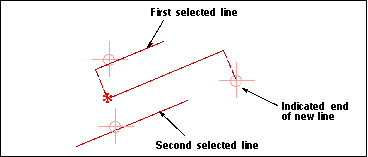
Select the first line. The endpoint nearest where you select this line determines the start point of the new line.
-
Select a line parallel to the first line.
A new line rubberbands parallel to the selected lines and midway between them. It begins at the projection of the closest endpoint of the first selected line onto the new line.
-
When the desired line is displayed, establish the length by specifying a cursor location, selecting geometry, or by entering a Length in the dialog bar.

To define a line through a point and normal to a face:
-
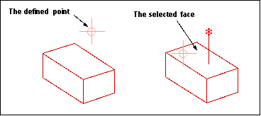
Define the point. The line rubberbands from the point.
-
Choose the Select Face option on the Point Method menu and select the face.
The line is created through the point and normal to the face, limited to its intersection with the face.
You can select the face first, but if you do, you will not see any rubberbanding. The line will just be created after you specify the point.
If the point is on the face, the line rubberbands normal to the face until you specify a limiting point or object.

You can use the Parallel at Distance From options to create a series of parallel lines. When you are creating multiple parallel lines, the offset distance can be measured either from the last created line (New) or from the original selected line (Original).
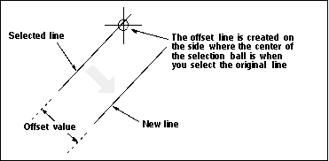
The value in the Offset field in the dialog bar determines the distance between the selected line and parallel line.
To define a line parallel to another line at a distance:
-
Turn String Mode OFF. You cannot create a line parallel at a distance when you are in string mode.
-
Select the base line, keeping the center of the selection ball on the side of the line that you want the offset measured in.
-
Enter the offset distance in the Offset field in the dialog bar and press <Return. The offset line is created.
-
To create another line at the same offset, press <Return again. To create another line at a different offset, key in that value and press <Return.