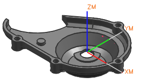
The Machine Coordinate System (MCS) determines the orientation and origin of tool paths for all operations in the orient group. The Work Coordinate System (WCS) determines most input parameters, such as From points, Clearance planes, and the tool axis.
The MCS has an initial position that is matched to the Absolute Coordinate System. The position of the MCS is saved in the part file. Each orient group (for example, MCS, MCS_MILL) defines the MCS that is necessary to machine a specific side of the part. If you move the MCS, you re-establish the base location for the subsequent tool path output points. The MCS has the following characteristics:
It stores the Reference Coordinate System (RCS).
It can store the Clearance plane, Lower Limit plane, and Avoidance points.
Operations stored under the MCS parent inherit the parameters specified in the MCS parent.
Operations moved from one MCS to another do not need to be generated to reflect the new orientation or origin.
The MCS is useful when you do the following:
Output the tool path in relation to the machine home position or any other frequently used setup location.
Reorient the machine tool axes to the workpiece.
Shift large parts for successive tool paths.
Set up parts which no longer have a reference point. For example, a tooling hole which has been machined away.
Reestablish setup position and orientation after rotary table movement and after compound axis movement.
Maintain critical dimensions otherwise lost to warping or tolerance buildup.
Establish basic and true positions.

|
Application |
Manufacturing |
|
Toolbar |
Insert→Create Geometry |
|
Menu |
Insert→Geometry |
|
Location in dialog box |
Geometry Subtype group→MCS |