NX CMM Inspection Programming is based on the NX Manufacturing architecture and offers many flexible ways to inspect a model. Although you can complete many tasks in different orders, the following represents a typical workflow.
-
Open an NX work part file to inspect and optionally, create tolerances and annotations in PMI.
-
Create an inspection file that references the NX work part file.
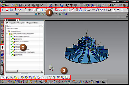

Insert, Feature, and Tolerance toolbars

Inspection Navigator

Navigator, Actions, and Operations toolbars
-
Retrieve a virtual CMM model, probe head, and probe from a library, and align the work part file as necessary.
-
Link to PMI to import:
-
Inspection features for all toleranced solids, based upon model geometry.
-
GD&T and direct tolerance information.
-
Automatic inspection paths on the toleranced features.
Note:
Any tolerance and feature names you define in PMI are retained in NX CMM Inspection Programming.
-
-
Add additional objects, including:
-
Features, such as points, lines, planes, cylinders, curves, surfaces, patterns, arcs, circles, spheres, cones, closed and open slots and tabs, and tori.

-
Tolerances, including:
-
Direct tolerances such as distance between, angle between, coordinate, diameter, radius, width, and cone angle.
-
Datum definitions and most GD&T tolerances.

-
-
Special features and inspection paths.


Constructed features
Inspection paths
Multi-feature paths
-
-
Calibrate and simulate your processes using NX collision detection.
-
Output your processes to a Dimensional Measuring Interface Standard (DMIS) file and then run the program on an actual CMM.
-
In a solution such as Dimensional Planning and Validation (DPV), statistically compare the results file created from your inspection run to the NX CMM Inspection Programming process.
-
Edit your process if necessary. You can delete, modify, or add new features, tolerances, probes, and inspection operations.